Common Line Cutting: What It Is, What It Saves, and When to Use It
Common line cutting shares one cut edge between two parts, cutting 85% fewer pierces and saving material and consumables on rectangular nesting jobs.
One of the first things plasma shop operators mention when I ask about their setup is consumable cost. Nozzles and electrodes burn through faster than expected, especially on jobs with many small parts. The usual response is “buy in bulk” or “change them on a tighter schedule.” The more effective response is to run fewer pierces per sheet.
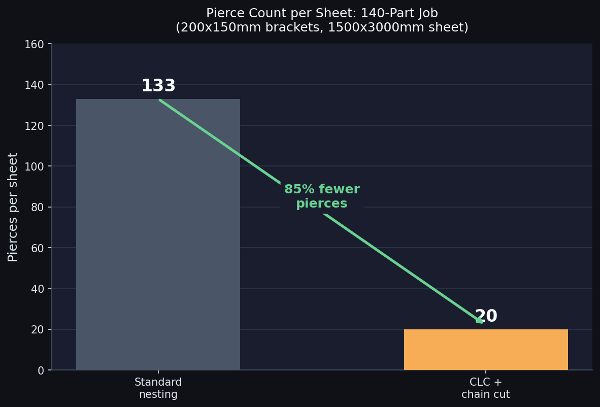
Common line cutting (CLC) makes this possible on rectangular and simple-shaped jobs. A single cut separates two adjacent parts simultaneously, eliminating the gap between them and reducing the total pierce count dramatically. On a sheet of 140 identical brackets, that difference is 133 pierces versus 20.
This post covers what CLC actually does, the specific numbers on material savings and consumable cost, and when it makes more sense than true-shape nesting.
What common line cutting actually does
Standard nesting places a kerf-width gap between every adjacent part. Each part gets its own complete cut perimeter, and the torch pierces once per part. The kerf between two neighbors is cut twice: once as the right edge of part A, and once as the left edge of part B.
CLC eliminates that gap. Two adjacent parts share one cut edge. The single cut path separates both parts at the same time, which means no material is consumed between them, one pierce handles what normally requires two, and the torch travels a shorter total distance across the sheet.
Chain cutting takes this further. The torch pierces once and snakes through every part in a row in one continuous path. On a 7-column × 20-row grid, that produces 20 total pierces instead of 140.
Material savings: the actual numbers
I calculated a representative job: 200×150mm steel brackets on a 1500×3000mm sheet with 2.5mm plasma kerf, consistent with Hypertherm Powermax85 cut charts for 6mm mild steel at 85A.
| Metric | Standard nesting | CLC + chain cut | Improvement |
|---|---|---|---|
| Parts per sheet | 133 | 140 | +5.3% |
| Sheet utilization | 88.7% | 93.3% | +4.7 pp |
| Pierces per sheet | 133 | 20 | -85% |
| Arc-on time per sheet | 47.9 min | 26.9 min | -44% |
Calculated at 2000 mm/min cutting speed, 20mm lead-in per pierce. See methodology note below.
The extra row comes from eliminating the 2.5mm kerf gap between each of the 19 standard-nesting row spacings: 19 × 2.5mm = 47.5mm recovered, enough to fit a 20th row (150mm tall). Hypertherm application data, cited in Canadian Metalworking, reports that CLC can take sheet utilization from 75% to 90% on rectangular-dominant jobs. The 4.7-point gain calculated here is conservative; it assumes the job already nests well because parts are rectangular.
Methodology: cut distance calculated as full perimeter × parts for standard nesting, and as outer perimeter + interior shared lines for CLC. Lead-in distance added per pierce. Arc-on time at 2000 mm/min. Does not include rapid traverse moves between parts, so actual total cycle time savings are higher.
Consumable cost savings
Plasma consumables wear primarily through piercing rather than through arc-on time. Hypertherm’s documentation states that Duramax torch electrodes and nozzles last 600 to 1,200 pierces before replacement. Electrode and nozzle are replaced as a set.
For a Powermax85 system, a genuine Hypertherm electrode+nozzle set is approximately $28. At 800 pierces average life, each pierce costs roughly $0.035 in consumable wear.
That number is small individually. It adds up across a year:
| Shop size | Sheets/week | Pierces/yr (standard) | Pierces/yr (CLC) | Annual savings |
|---|---|---|---|---|
| Small shop | 5 | 34,580 | 5,200 | $1,028 |
| Mid-size shop | 20 | 138,320 | 20,800 | $4,113 |
| Large shop | 60 | 414,960 | 62,400 | $12,340 |
Assumes 133 parts/sheet at 133 pierces standard, 20 pierces/sheet with CLC + chain cutting. Consumable cost $0.035/pierce (Powermax85 electrode+nozzle set at $28, 800 pierce life).
These are conservative because they exclude z-axis head movement wear (torch lifts between parts) and the cost of mid-run consumable failure, which can require scrapping the current sheet. Reducing pierce count also reduces the frequency of abrupt arc starts, which are the most mechanically stressful events for the plasma system.
Cut time savings
The 44% reduction in arc-on time per sheet is the figure shops should pay attention to. For a shop running 20 sheets per week, that’s roughly 175 arc-on hours saved annually — counting only the shorter cut distance, not the faster cycle from fewer torch lifts.
The time saving is more significant on plasma than laser because plasma machines cut at 1,000 to 3,000 mm/min on mid-gauge steel, while fiber lasers run 10,000+ mm/min on thin material. Every unnecessary pierce and traverse is a larger fraction of the total job time on a plasma table. For oxyfuel cutting, the benefit is even larger, because each pierce requires a separate pre-heat cycle that can take 15 to 30 seconds on thick plate.
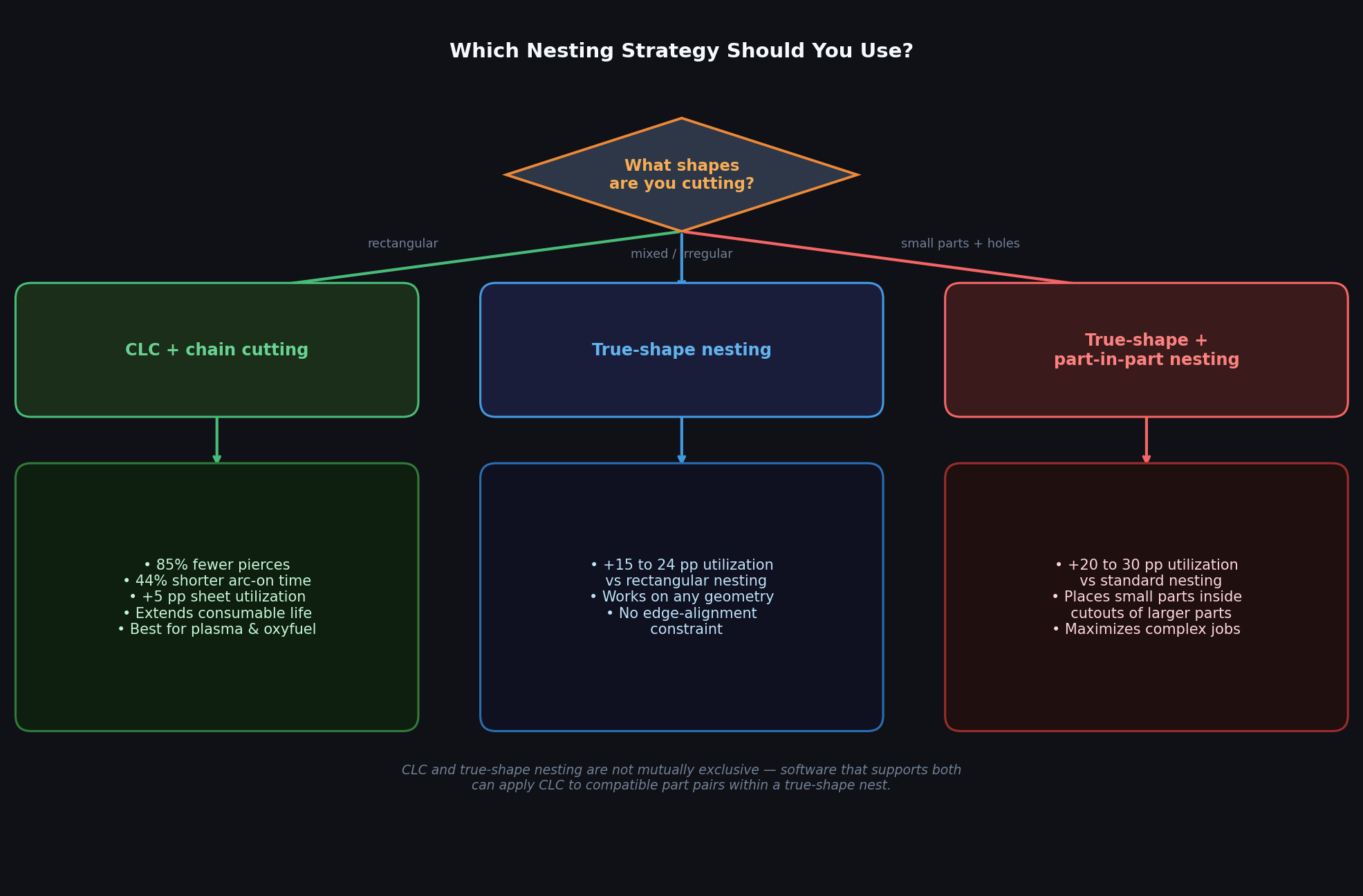
When CLC makes sense vs. true-shape nesting
CLC has a narrow sweet spot: it works best when you’re cutting many identical or geometrically compatible rectangular shapes. When parts are irregular, the benefit drops sharply.
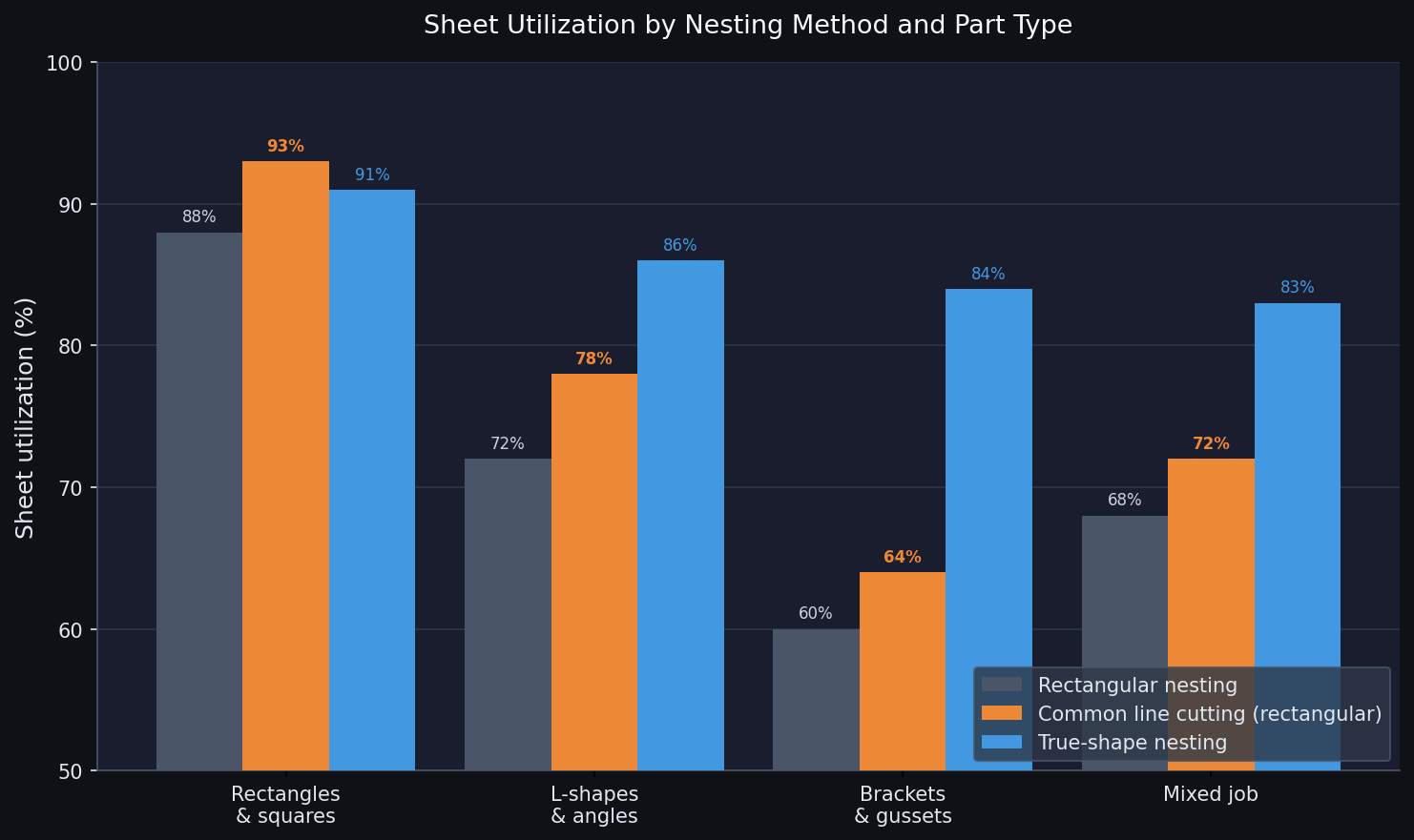
For rectangular parts, CLC adds roughly 5 percentage points over standard rectangular nesting. For L-shapes and complex brackets, true-shape nesting outperforms CLC rectangular nesting by 8 to 20 percentage points. This gap exists because CLC is an optimization applied on top of rectangular nesting, while true-shape nesting is a fundamentally different approach: it uses the actual part outline to find arrangements that rectangular nesting structurally cannot achieve.
Most shops don’t cut purely rectangular parts. A typical fabrication job mixes brackets, plates, flanges, and angles on the same sheet. For that workload, true-shape nesting consistently recovers more material than CLC on rectangular layouts. For shops running dedicated rectangular production — flat bar sections, tile-like panels, uniform shims, standard structural shapes — CLC is worth implementing.
The two techniques are not mutually exclusive. Software that supports both true-shape nesting and CLC can apply CLC to compatible part pairs within a true-shape nest, recovering the last few percentage points on mixed jobs.
Practical limitations
CLC requires straight, aligned shared edges. Parts must share a compatible edge to apply CLC. Two circles, two irregular brackets, or two rectangles oriented differently cannot share a cut line without distorting part geometry. CLC software checks for edge compatibility automatically, but the technique is structurally limited to shapes with straight parallel edges that can be aligned.
Only interior edges benefit. The outer perimeter of the grid is still cut as normal single-part edges. On small grids, the boundary is a large fraction of total cut length, which reduces the proportional savings.
Lead-in placement changes. Standard nesting places a lead-in on the outer perimeter of each part. With CLC and chain cutting, lead-ins are placed at the start of each chain. The chain entry point needs a clean pierce location on the sheet, and some nesting configurations will place pierces in tighter spots that require attention. On thick plate especially, a poorly-placed pierce can produce a blast pit that degrades the nearby part edge.
Not all nesting software supports it. CLC requires the optimizer to group two parts with a zero-gap shared edge and treat them as a single cutting group. That’s a different operation from just minimizing part spacing. Purpose-built CNC nesting tools handle it. General-purpose or lightweight tools typically do not.
For shops cutting irregular parts, true-shape nesting delivers comparable or better material savings without the geometry constraints. For shops cutting rectangular jobs where kerf compensation and tight spacing already achieve good utilization, CLC’s primary value is the pierce count reduction and its downstream effect on consumable life and cycle time.
FAQ
Is common line cutting the same as chain cutting?
Related but distinct. Common line cutting means two parts share one cut edge with zero gap. Chain cutting means the torch moves through multiple parts in sequence without stopping or re-piercing, connected by small bridges or by the shared cut path itself. CLC often enables chain cutting, because parts with shared edges allow continuous torch travel. Chain cutting can also be applied without CLC, using micro-joint bridges that hold parts to the skeleton until the cut chain is complete.
Does common line cutting affect part accuracy?
It can on plasma, because the plasma arc creates a heat-affected zone on both sides of the cut. When two parts share an edge, both adjacent faces are exposed to that heat simultaneously. For precision-tolerance parts, test CLC on samples before running production. For structural parts where tolerance is ±0.5mm or more, CLC typically has no meaningful effect on accuracy.
How does common line cutting compare to part-in-part nesting?
They solve different problems. CLC reduces the gap between adjacent parts on the exterior of shapes. Part-in-part nesting places smaller parts inside the holes or cutouts of larger parts — for example, fitting a small disc inside the circular cutout of a flange. Part-in-part nesting is most valuable for jobs with large interior cutouts. CLC is most valuable for solid rectangular shapes. On complex jobs, both techniques together can push utilization above 95%.
What material thickness works best with CLC?
Plasma CLC is most practical on mild steel 4 to 20mm. On thin materials under 3mm, laser cutting is more common and the consumable savings argument weakens since laser piercing produces far less electrode wear than plasma. On very thick material (25mm and above), longer lead-ins and higher thermal input mean more spacing is needed between parts anyway, which limits CLC applicability.
My parts are not all rectangular. Is CLC still worth investigating?
Run the utilization numbers on your actual job mix. If a portion of your production is rectangular components in the same material, those specific jobs are CLC candidates even if the rest of your work is irregular. For the irregular work, true-shape nesting and accurate kerf settings will recover more material than trying to force CLC onto geometry it wasn’t designed for. The material waste cost calculator can help you quantify which improvement has the larger financial impact for your shop specifically.