Cut Sequence in Laser Cutting: Why the Order You Cut Parts Matters
Bad cut sequence causes sheet warping, part tipping, and head collisions in laser cutting. Learn how cut order affects distortion, safety, and cycle time.
The last time I watched a laser cutting job fail, nothing was wrong with the machine settings. Power, speed, focal point, assist gas pressure were all dialed in. The operator had been cutting the same 2 mm stainless for years. The problem was that his nesting software had generated a sequential cut pattern, marching left-to-right across the sheet, and by the time the head reached the right side, the steel had soaked up enough heat to bow at the corners. Every part on the right half needed to be flattened before it went to the press brake.
Cut sequence is the order in which your laser cuts each part, contour, and internal feature on a nest. Most operators tune kerf, pierce settings, and lead-ins carefully, then let the nesting software decide the rest. That default is often fine for thick plate. For thin sheet, stainless, or any nest with small parts, it is not.
Bad cut sequence causes three problems, each with real cost:
- Heat accumulation and sheet distortion
- Part tipping and cutting head collisions
- Excess rapid travel time
Each one is controllable once you understand what drives it.
Why Sequential Cut Order Builds a Heat Wave
When you cut parts row-by-row, each cut deposits heat into the sheet. The next cut goes to the adjacent zone, which is still warm from the previous cut. By part 10 or 12 in a row, the local area is significantly hotter than ambient, and the residual thermal stress is enough to warp thin material.
I modeled this for a nest of 20 parts on 3 mm mild steel, with each part taking roughly 8 seconds to cut. Sequential cutting: 2-second rapid to the next adjacent part. Distributed cutting: a skip-4 pattern that jumps across the sheet before cycling back. The difference is not subtle.
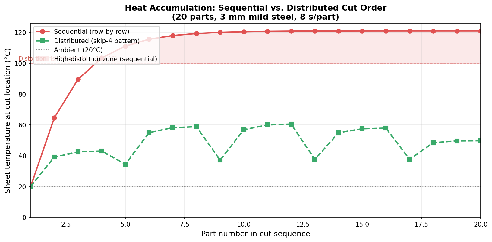
Sequential cutting reached a local sheet temperature of 121°C by part 10 and plateaued there for the rest of the nest. The distributed pattern peaked at 60.5°C, roughly half the thermal load at any point in the sheet.
That 60°C gap is the difference between a flat part and one that needs straightening before bending.
A 2024 study published in Machines (MDPI, vol. 12, no. 3, art. 206) confirmed that sequential heat accumulation in thin-walled sheet metal laser cutting causes both dimensional distortion and excessive melting near the cut edge. The researchers built a temperature prediction model for the next pierce point, with less than 10% prediction error, and showed that switching process parameters mid-job based on predicted local temperature can control distortion without sacrificing throughput.
Thin material amplifies the problem. On sheets under 2 mm, the thermal mass is too low to absorb even a short sequential run without visible lifting at the sheet edges. Stainless compounds it further because it has roughly a third of the thermal conductivity of mild steel, so heat lingers in the zone rather than spreading outward quickly.
Practical rule: for any sheet under 3 mm, or any run of stainless or aluminum, configure your nesting software to use a distributed or randomized cut sequence rather than the default row-by-row pass.
Cut Sequence and the Part Tipping Problem
The second consequence of cut order is physical. When a small part is fully cut free from the sheet, it sits on the slat table. If it tips, the cutting head hits it.
Slats are typically spaced 50–75 mm (2–3 inches) apart. Any part with at least one dimension under 150 mm (6 inches) may only be supported by one or two slats after it is released from the surrounding material, making it unstable. According to nesting expert Mike Boggs, writing in The Fabricator, a tipped part can project 20 mm upward - more than enough to impact a cutting head moving at full rapid speed.
The cost of a head collision ranges from a few hundred dollars in consumables to $10,000–$30,000 for a complete head replacement if the internal optics or autofocus mechanism are damaged. Collision accounts for approximately 40% of all laser head damage incidents.
Cut sequence controls when each part becomes free-floating. If you cut small parts last, after surrounding material has already been removed, those parts lose their support and tipping is nearly guaranteed. If you keep small parts attached via micro-joints until the end of the job, or sequence them while adjacent material still stabilizes the sheet, the risk drops substantially.
Here is a practical reference for tipping risk by part size:
| Part minimum dimension | Slat support | Tipping risk | Recommended action |
|---|---|---|---|
| > 300 mm | 4+ slats | Very low | Standard cut sequence |
| 150–300 mm | 2–3 slats | Low | Check orientation relative to slat direction |
| 75–150 mm | 1–2 slats | High | Add micro-joints; cut before outer skeleton is removed |
| < 75 mm | Less than 1 slat | Very high | Micro-joints required; consider slug-destruct on large internal slugs |
Large internal cutouts follow the same logic. A 200 mm square hole releases a 200 mm square slug. That slug is heavy enough to fall cleanly if it has clearance, or wide enough to tip up and block the cutting path if it rests on a slat edge. Slug-destruct sequences cut the slug into smaller pieces before the final perimeter releases it, eliminating the tipping risk from the cutout itself.
Rapid Travel and Cycle Time
The third factor is efficiency. Sequential cutting minimizes rapid travel distance because the next part is always adjacent. Distributed cutting adds travel.
The tradeoff is real. On a dense nest of 20 parts, switching from sequential to a skip-4 distributed pattern adds roughly 15–20% to total rapid travel distance. On a large sheet with long cross-sheet moves, that can add a few minutes to cycle time.
The practical answer is to differentiate within the nest. Large parts (over 300 mm in all dimensions) on material thicker than 3 mm rarely distort from sequential cutting and are too heavy to tip. Cut those sequentially. Small parts, and thin material of any size, need the distributed approach. Some nesting software lets you configure cut sequence mode per size range within the same nest.
A Practical Cut Sequence Workflow
Once you have a framework, the decision is fast. Here is how I work through a new nest:
flowchart TD
    A[New nest layout ready] --> B{Any parts smaller\nthan 150 mm?}
    B -->|Yes| C[Flag for micro-joints\nor slug-destruct]
    B -->|No| D[Standard cut order OK]
    C --> E{Sheet thickness\nunder 3 mm?}
    D --> E
    E -->|Yes| F[Enable distributed\ncut sequence]
    E -->|No| G[Sequential order\nacceptable]
    F --> H[Cut internal features\nbefore outer contours]
    G --> H
    H --> I[Review cut simulation\nif software supports it]
    I --> J[Export and cut]
The step most operators skip is H: cutting internal features before outer contours. When the outer contour is cut first, the part is released and loses the support of the surrounding sheet. Internal cuts then run on a floating piece that can shift, causing the head to lose focus or clip a lifted edge. Internal-first ordering is not always the default in nesting software. Check your sequencing settings explicitly.
The part spacing you set during nesting also interacts with cut sequence. Parts spaced only 2 mm apart leave almost no room for heat to dissipate between adjacent cuts, which effectively turns even a distributed sequence into a sequential thermal pattern. Spacing parts 4–6 mm apart gives the sheet enough thermal separation for the distributed pattern to work as intended.
How Lapas Handles Cut Sequence
Lapas cuts internal features, and parts nested inside holes, before outer contours in its exports. If you export G-code, a Simulate button plays the toolpath back before you run it. Patterns beyond that, such as a distributed order for small parts on thin sheet, belong in your CAM, which is where the nested DXF goes for production.
FAQ
Does cut sequence matter for thick plate (over 10 mm)? For thick plate, thermal mass is high enough that sequential cutting rarely causes visible distortion. The bigger risk is cut quality degradation on the trailing edge as the sheet heats up over a long job. Distributed sequence still helps on very long runs of thick plate, but it is not as critical as it is for thin sheet.
How do I know if my parts are tipping during a job? Tipping often shows up as a sudden change in cut quality mid-job, or as a collision alarm. If collisions happen consistently in the second half of a nest, after the surrounding material has been removed, part tipping is the likely cause. Switching to micro-joints on affected parts and rerunning confirms it.
What is a slug-destruct sequence? A slug-destruct sequence cuts a large internal slug into multiple smaller pieces before the final perimeter cut releases it. This prevents the slug from tipping upward into the cutting path. Most professional nesting software applies slug-destruct automatically for internal slugs over a set size, typically 100–150 mm in any dimension.
Can I use common-line cutting and a distributed sequence together? Common-line cutting shares an edge between two adjacent parts, which locks their spatial relationship. Those pairs are cut as a unit, and the sequence optimization applies at the unit level rather than the individual part level. Distributed sequence still works, but it operates on units rather than individual contours.
Does cut direction (clockwise vs. counterclockwise) affect distortion? Cut direction has a measurable effect on surface roughness and dross formation on some materials, particularly stainless. It does not significantly affect thermal distortion. The dominant factor is how long the laser spends in any one zone of the sheet, not the rotational direction of individual contours.
Cut sequence is decided downstream of the nest, but the nest decides what sequences are even available. Lapas laser cutting nesting exports a DXF you can sequence in LightBurn or RDWorks.