Lead-In and Lead-Out Settings for CNC Cutting: Stop Marking Your Parts
Lead-in and lead-out settings for laser, plasma, and oxyfuel cutting: what each type does, minimum lengths by process and thickness, and four failure modes to fix.
I’ve talked to operators who had been running the same machine for three years and still couldn’t explain the small burn mark that appeared at exactly the same position on each finished part. After some digging it was always the same cause: the pierce and lead-in were landing too close to the part edge.
The fix is straightforward once you understand what lead-in and lead-out settings actually control. This post explains the types, the recommended lengths by process and material thickness, and the four failure modes that show up when settings are wrong.
The short answer on lead-in settings for laser and plasma cutting
An arc lead-in at 1.5 to 3 times the kerf width eliminates pierce marks on finished part edges while keeping the entry path short enough to nest tightly. For standard plasma that minimum rises to 6 mm regardless of kerf, and for oxyfuel it starts at 15 mm. Place the lead-in entry point entirely in the scrap zone, not on the part edge and not in an adjacent part’s space.
What lead-in and lead-out actually do
Every thermal cut starts with a pierce: the beam or arc burns through the material from the top surface. The pierce leaves a rough, slightly over-burned entry point that does not match the cut quality on the rest of the contour. During the pierce, the machine is ramping up current, gas flow, and cut speed, so the entry zone is always a transitional imperfection.
The lead-in path runs from the pierce point to the actual part boundary. By the time the cutting head reaches the part outline, parameters have stabilized and the cut quality matches the rest of the contour. The lead-in is entirely in the scrap area, so any pierce defects stay off the finished part.
The lead-out serves the opposite function. At the end of a closed contour, the cutting head returns to its starting point. Without a lead-out, the final pass overlaps the entry point, which can create a visible notch at the closure or, on plasma, damage the nozzle when the torch cuts through material that has already separated.
Lead-in types and when to use each
CAD/CAM systems typically offer four geometries. Amada’s AP100 software documentation classifies six lead-in types, of which these four appear across virtually all CNC sheet-cutting platforms:
Line. A straight-line approach at a set angle, usually 30 to 45 degrees off the contour tangent. The simplest option and sufficient for most laser cutting on thin to medium material. The risk is the sharp direction change at the entry point: if the cut speed hasn’t fully stabilized, that kink shows as a visible artifact.
Arc. The lead-in curves smoothly into the part contour tangentially, matching the direction of travel at the entry point. This eliminates the kink artifact and gives the cleanest entry quality of any type. Arc lead-ins are the default recommendation for most laser and high-definition plasma cutting.
Hook. A perpendicular pierce followed by a 90-degree arc into the contour. Used in tight spaces where a longer angled lead-in doesn’t fit. The perpendicular pierce helps with some material behaviors but creates a more abrupt direction change than a smooth arc.
Cross-cut. The pierce extends into a short straight path before the head turns onto the part outline. This type is standard for thick material, generally above 12 mm for laser and throughout the usable thickness range for oxyfuel, where the pierce hole is wider and must be moved well away from the contour.
For internal cutouts (holes, slots, pockets) the same types apply but the entry point is constrained by the available area inside the contour. On small holes, the available space may be too tight for any lead-in, in which case cutting directly on the contour is the only practical option.
Lead-in length by process and material thickness
The table below gives minimum lead-in lengths derived from process kerf widths and documented ramp-up distances. For laser processes the rule is approximately max(2× kerf, process minimum). For plasma and oxyfuel, material thickness constrains the minimum further because the pierce diameter is larger and parameter ramp-up takes longer.
| Process | Thickness | Kerf | Min lead-in | Recommended type | Lead-out |
|---|---|---|---|---|---|
| Fiber laser | 1–3 mm | 0.15 mm | 0.5 mm | Arc | Not required |
| Fiber laser | 4–8 mm | 0.20 mm | 0.7 mm | Arc | Not required |
| Fiber laser | 9–20 mm | 0.30 mm | 1.0 mm | Arc / Cross-cut | 0.5–1 mm arc |
| Fiber laser | 21+ mm | 0.50 mm | 1.5 mm | Cross-cut | 1–2 mm arc |
| CO2 laser | 1–3 mm | 0.20 mm | 0.8 mm | Arc | Not required |
| CO2 laser | 4–8 mm | 0.30 mm | 1.0 mm | Arc | Not required |
| CO2 laser | 9–20 mm | 0.50 mm | 1.6 mm | Arc | 0.5–1 mm arc |
| CO2 laser | 21+ mm | 0.80 mm | 2.4 mm | Cross-cut | 1–2 mm arc |
| HD plasma | 1–3 mm | 1.00 mm | 3.0 mm | Arc | 1–2 mm line |
| HD plasma | 4–8 mm | 1.50 mm | 3.8 mm | Arc | 2–3 mm line |
| HD plasma | 9–20 mm | 2.00 mm | 5.8 mm | Arc | 3–4 mm line |
| HD plasma | 21+ mm | 2.50 mm | 12.0 mm | Line | 4–6 mm line |
| Standard plasma | 1–3 mm | 2.00 mm | 6.0 mm | Arc | 2–4 mm line |
| Standard plasma | 4–8 mm | 3.00 mm | 7.5 mm | Arc | 4–6 mm line |
| Standard plasma | 9–20 mm | 4.00 mm | 10.0 mm | Arc | 5–8 mm line |
| Standard plasma | 21+ mm | 5.00 mm | 12.5 mm | Line | 6–10 mm line |
| Oxyfuel | 4–8 mm | 2.50 mm | 15.0 mm | Line | 5–10 mm line |
| Oxyfuel | 9–20 mm | 4.00 mm | 15.0 mm | Line | 10–15 mm line |
| Oxyfuel | 21+ mm | 6.00 mm | 15.0 mm | Line | 15–25 mm line |
The chart below makes the scale difference visible. Laser lead-in lengths look small next to plasma and oxyfuel because the kerf is narrower and the pierce hole is much smaller. A fiber laser piercing 3 mm mild steel leaves a hole roughly 0.3 to 0.5 mm wide. A standard plasma torch on the same material produces a hole 2 to 3 mm across, which needs significantly more lead-in distance before the cut stabilizes.
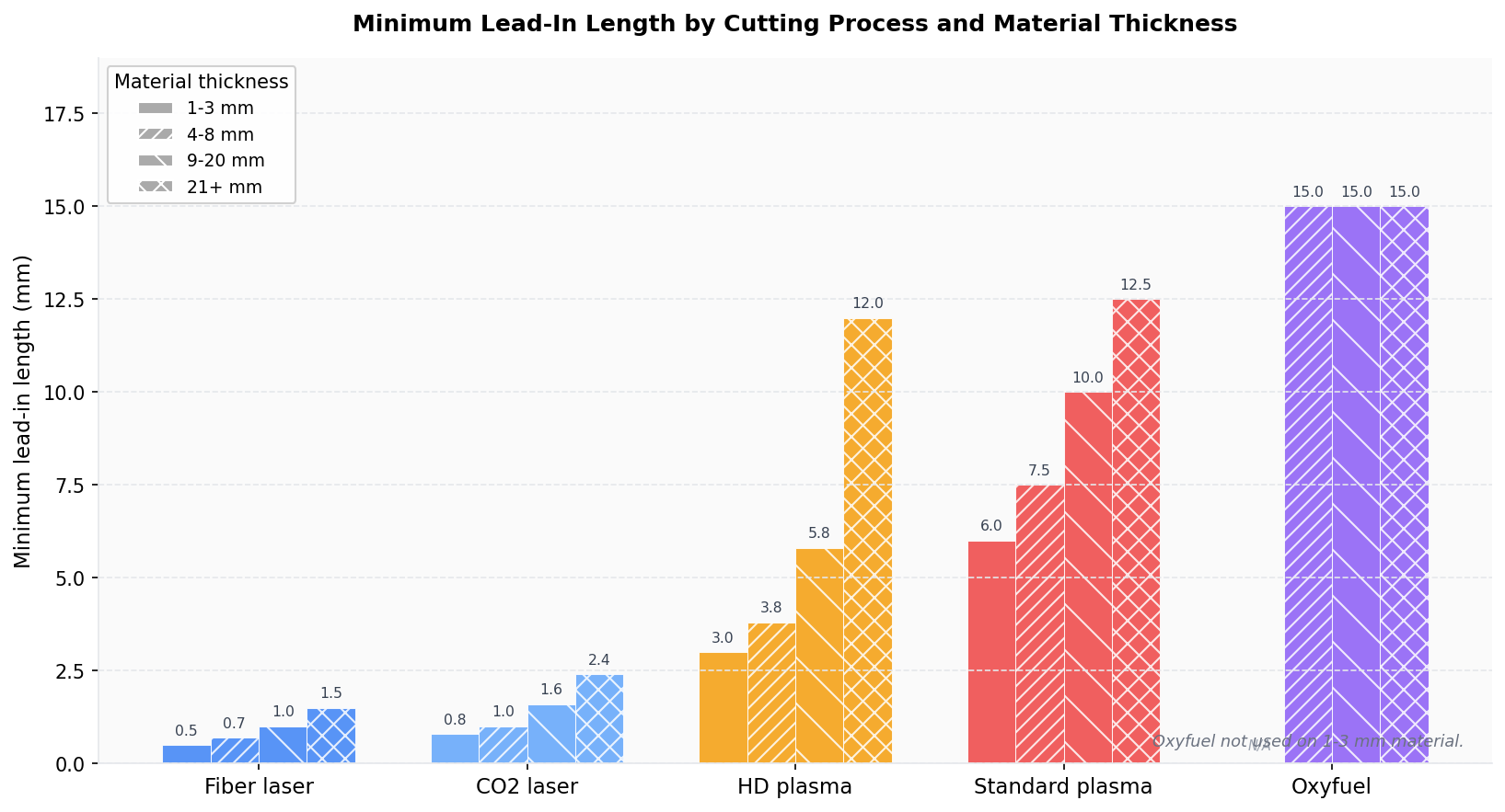
For kerf width values specific to your machine and material, the kerf compensation guide covers how to measure it directly rather than relying on published specifications.
The lead-in path needs to clear adjacent parts
A lead-in that fits the part being cut can still cause a problem if its path enters the space reserved for a neighboring part. The gap between two nested parts must be at least as large as the lead-in length in the direction the lead-in travels, not just the kerf width.
For standard plasma with a 10 mm lead-in, you need at least 10 mm of clear space in the direction the lead-in travels. Nesting software that understands lead-in geometry accounts for this automatically during placement. If your software doesn’t, you have to set a larger part gap to keep the lead-in path out of neighboring parts. The part spacing guide covers the gap calculation in full, but the practical rule is: your part gap must accommodate both the thermal spread and the lead-in geometry.
The four failure modes from wrong lead-in settings
Pierce mark on the finished part. The lead-in is too short, or there is no lead-in at all. The pierce happens at or near the part outline. The rough entry point lands on the part surface rather than in the scrap zone. This shows as a round burn mark or rough spot at one consistent location on the part edge. Fix: increase lead-in length until the pierce point sits fully in scrap material.
Entry notch. The lead-in type creates an abrupt direction change where the straight approach meets the curved contour. The cutting head changes direction before the cut velocity has fully matched the contour path, leaving a small V-shaped notch at the entry point. More common with line lead-ins on curved contours. Fix: switch to an arc lead-in that arrives tangentially and carries the cut into the contour without a direction change.
Arc stretching and nozzle damage (plasma only). If the lead-out is too long and a finished part drops from the sheet before the torch reaches the end of the lead-out path, the torch tries to cut through empty space or a tilted part edge. The arc stretches, voltage spikes, and the nozzle orifice burns irregular. Hypertherm’s process documentation specifically flags lead-outs longer than 1.5 times the kerf width as a nozzle damage risk. Fix: keep lead-out length at or below 1.5 times kerf width. If the closure point still shows roughness, check whether the power ramp-down is configured, not whether the lead-out is long enough.
Lead-in invades adjacent part. When parts are nested tightly and lead-in direction is not accounted for, the lead-in path crosses into the zone of a neighboring part. The torch or laser adds an unintended cut line to the wrong part. Fix: either increase the gap between parts or configure nesting software to rotate lead-in entry directions toward existing gaps or the sheet skeleton rather than toward neighbors.
Lead-in type selection: a decision guide
| Situation | Recommended type | Notes |
|---|---|---|
| Fiber / CO2 laser, thin to medium (1–12 mm) | Arc | Default for all closed contours |
| Fiber / CO2 laser, thick (12+ mm) | Cross-cut | Move pierce well away from outline |
| Internal hole, laser, diameter > 10 mm | Arc (tangential to hole circle) | Tangent entry avoids overcut at start |
| Internal hole, laser, diameter < 10 mm | None or short line | Geometry too tight for arc |
| HD plasma, all thicknesses | Arc | Longer than laser; 3–6 mm range |
| Standard plasma, thin to medium | Arc | 6–10 mm; longer for ramp-up |
| Standard plasma / HD plasma, very thick (25+ mm) | Line | Arc geometry harder to control at depth |
| Oxyfuel, all thicknesses | Line | Preheat phase requires straight approach |
Lead-out: skip it on laser, use it on plasma
For fiber and CO2 laser cutting on thin to medium material, lead-out is typically unnecessary. Modern laser machines ramp down power before the head completes the closed contour, and the result at the closure point is clean enough for most fabrication tolerances.
For plasma and oxyfuel, lead-out is standard. The arc needs to exit the part boundary before the torch turns off; otherwise the power-down phase happens on the part edge, leaving rougher finish at closure. The lead-out also reduces the risk of part drop catching the torch if the freed part tilts before the torch finishes its exit path.
When configuring nesting software, check whether lead-outs are set separately from lead-ins. Many systems default to “None” for lead-outs and require explicit configuration per process and material.
FAQ
What happens if I run with no lead-in at all? The pierce lands directly on the part outline. The pierce leaves a burned, slightly over-cut entry point on the part edge. On plasma, the entry also shows a rougher zone because the arc is ramping up while already on the contour. On laser, it typically shows as a small spot burn or a slightly widened kerf at one point.
Can lead-in length affect material utilization? Yes, but less than most operators expect. A 10 mm plasma lead-in adds roughly 10 mm of spacing in the direction it travels, which affects how tightly parts can be nested. On a sheet of 200 small parts, that extra spacing reduces yield by 3 to 5%. Nesting software that tracks lead-in geometry can rotate entry directions toward existing scrap gaps or the sheet edge, minimizing the yield penalty.
Why does my CAM software show different lead-in settings for internal versus external contours? External contours (the outer boundary of the part) use standard lead-in rules. Internal contours (holes, slots) need shorter lead-ins because the available interior space is limited. For holes smaller than twice the lead-in length, most systems automatically disable the lead-in or switch to a minimal straight-line entry.
What lead-in type works best for small circular holes? For holes larger than roughly 20 mm on plasma and 8 mm on laser, an arc lead-in placed tangentially to the hole perimeter is standard. For smaller holes, a short line lead-in or no lead-in is more practical. Avoid cross-cut lead-ins inside small holes: the cross path has nowhere to go and can damage the hole geometry.
How do I tell whether the defect on my parts is from the pierce, the lead-in type, or something else? Check the location and shape. A round burn at one consistent point on the part edge is a pierce mark (lead-in too short). A V-shaped notch at the entry point is a line-to-contour kink (switch to arc). Roughness spread across the entire contour is a parameter issue (cut speed, gas pressure, power), not a lead-in problem. Roughness only at the closure point is a lead-out issue or a power-ramp misconfiguration.
Lead-ins need room, and room is decided by the nest. Plasma cutting nesting in Lapas lets you set spacing that accounts for them.