Part Rotation in Nesting Software: The Setting That Decides How Much Material You Waste
How rotation settings in nesting software affect material utilization — with calculated yield data by aspect ratio, grain direction trade-offs, and a decision guide.
I’ve reviewed hundreds of nesting jobs submitted by operators using Lapas. The single most common source of avoidable material waste isn’t bad DXF files or wrong kerf settings. It’s rotation left at “no rotation” or “90 degrees only” on jobs where the parts are long strips or irregular polygons that would interlock much more tightly if the optimizer were allowed to turn them.
For near-square parts, the rotation setting barely matters — maybe 0.5% utilization difference. For a 4:1 aspect ratio part, the difference between no rotation and 90-degree rotation can be 14 percentage points. On a sheet that costs $80, that’s $11 of material recovered or lost per sheet, based purely on a checkbox in the settings panel.
This post covers what rotation settings actually do, when to restrict them, and how to choose the right one for your job.
What rotation settings mean in practice
Most nesting software offers some combination of these modes:
| Setting | What it allows | Best for |
|---|---|---|
| No rotation | Parts stay in their original file orientation | Grain-critical materials, parts with directional features |
| 180° only | Parts can be flipped end-to-end | Symmetric parts where only mirroring matters |
| 90° steps (0/90/180/270) | Full orthogonal rotation | Most laser and plasma jobs |
| Custom step (e.g., 15°, 45°) | Rotation at fixed intervals | Angled parts, trapezoidal shapes |
| Free rotation | Any angle, continuous | Organic shapes, gaskets, freeform profiles |
The setting that produces the best utilization is almost always free rotation. The setting that produces the fastest computation is no rotation. The practical sweet spot for most shops is 90° steps, because it unlocks most of the orientation benefit at a fraction of the computation cost.
The numbers: utilization by aspect ratio
I ran a grid-packing simulation on a 1000×2000 mm sheet across four representative part types to show how much rotation actually changes material utilization. “No rotation” means the part is placed in its natural landscape orientation (as it comes out of the CAD file). “With rotation” means the optimizer can also try the part rotated 90°.
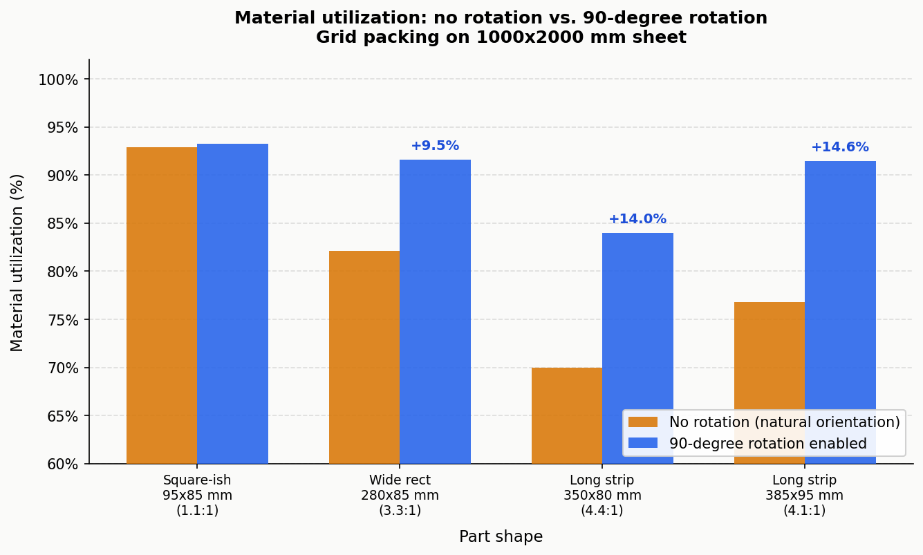
| Part | Size | No rotation | 90° rotation | Gain |
|---|---|---|---|---|
| Square-ish | 95×85 mm (1.1:1) | 92.9% | 93.3% | +0.4% |
| Wide rectangle | 280×85 mm (3.3:1) | 82.1% | 91.6% | +9.5% |
| Long strip | 350×80 mm (4.4:1) | 70.0% | 84.0% | +14.0% |
| Long strip | 385×95 mm (4.1:1) | 76.8% | 91.4% | +14.6% |
These are exact calculations for a uniform grid-packing arrangement, not estimates. The near-square part (95×85) is essentially the same in either orientation. The long strips improve by 9-15 percentage points simply because landscape orientation strands wide wasted columns at the sheet edge, while portrait orientation fills the sheet more evenly.
For irregular polygons, the gains from going beyond 90° rotation (to free rotation) are documented in research on polygon nesting algorithms. Burke et al. (2007), European Journal of Operational Research, showed that rotation constraints are the primary variable affecting utilization in irregular shape nesting — more so than algorithm choice. For concave parts with interlockable geometries, free rotation adds another 5-15% over fixed-angle rotation.
For rectangular parts, 90° rotation already achieves the optimal orientation, so free rotation offers no additional gain.
When to restrict rotation
Enabling full rotation on every job would be wrong. There are three legitimate reasons to restrict it.
Grain direction in sheet metal. Rolled steel and aluminium have mechanical properties that vary with the rolling direction. Parts with bend lines should be oriented so the bend runs perpendicular to the grain — this reduces cracking risk and allows tighter bend radii. A 3 mm stainless bracket that tolerates a 5 mm bend radius perpendicular to grain may crack at the same radius if bent parallel to grain. When grain direction matters, lock parts to 0°/180° rotation only, so the grain relationship is preserved.
Visible grain in wood and decorative materials. Plywood face veneer, brushed aluminium panels, and anodised sheet often look wrong if some parts are rotated 90° relative to others. This is an aesthetic constraint, not a mechanical one, but it’s just as real for shops doing decorative work.
Asymmetric functional features. Parts with asymmetric hole patterns, text engravings, or directional surface finishes may need to stay in a specific orientation for downstream assembly to work. This case is actually rarer than operators think — most parts are symmetric enough that rotation doesn’t affect function — but it does come up.
Outside these three cases, restricting rotation is usually a mistake that costs material for no benefit.
Choosing your rotation setting
The decision tree below covers most situations:
flowchart TD
    A[Does this part have a bend line\nor grain-critical direction?] -->|Yes| B[Will bending fail if grain\ndirection changes?]
    A -->|No| C[Does the part have\nasymmetric features?]
    B -->|Yes| D[Use 0°/180° only.\nGrain direction locked.]
    B -->|No| E[90° steps are safe.\nTest a sample bend first.]
    C -->|Yes, text or\ndirectional finish| F[Use no rotation or\n0°/180° only.]
    C -->|No or uncertain| G[Is the part\nnear-square, below 1.5:1?]
    G -->|Yes| H[Any rotation setting.\nDifference is under 2%.]
    G -->|No, aspect ratio\nover 1.5:1| I[Is the part rectangular\nor convex?]
    I -->|Rectangular\nor convex| J[90° steps.\nFree rotation adds nothing.]
    I -->|Irregular, concave,\nor freeform| K[Free rotation.\nExpect 5–15% extra yield.]
Most laser-cut parts with no bend requirements fall into the J or K branch. The practical default for a laser cutting shop on mild steel, acrylic, or plywood is: 90° steps for rectangular and near-rectangular parts, free rotation for irregular profiles.
Free rotation vs. step rotation: the computation trade-off
Free rotation means the algorithm has to evaluate the part’s no-fit polygon (the region where it cannot be placed without overlapping other parts) at potentially thousands of angles per placement decision. For a complex irregular polygon, this is computationally heavy.
90° steps means only four orientations are evaluated. The nested result is computed significantly faster, and for most rectangular and near-rectangular parts, the utilization is identical to free rotation.
The practical guidance: start with 90° steps on your first run. If the utilization is below what you’d expect given your part shapes, switch to free rotation and compare. For simple parts, 90° steps and free rotation will produce the same result. For complex irregular shapes, free rotation will do better, and the extra computation time (typically 20-60 seconds on a modern machine) is worth it on expensive material.
Lapas shows the utilization percentage on every completed nest. If you’re running 90° steps and getting below 82% on a job that has non-rectangular parts, free rotation will almost always close that gap.
Three rules that cover 90% of jobs
Rule 1: Aspect ratio under 1.5:1 — rotation barely matters. Square-ish parts pack nearly the same in any orientation. Don’t overthink it; 90° steps is fine.
Rule 2: Aspect ratio over 3:1 — always check if rotation is enabled. Long strips, bars, and slats have the most to gain from orientation flexibility. The data above shows gains of 9-15% just from enabling 90° rotation on these parts.
Rule 3: Irregular shapes with concavities — use free rotation. When parts can interlock (L-shapes, brackets, T-profiles), free rotation allows the optimizer to find angles where they mesh tightly. Restricting to 90° steps on these parts leaves material on the table that free rotation can recover.
FAQ
What happens if I enable free rotation on parts that need grain direction?
The optimizer will rotate them to whatever angle maximizes utilization, ignoring grain direction entirely. For structural parts with bend requirements, this produces cuts that may fail in use. Always lock grain-critical parts to 0°/180° before running a nest.
Should I set rotation at the job level or per part?
Per part, when you have a mixed job. Most nesting tools, including Lapas, let you set rotation constraints individually. A job with both grain-critical flanges and unconstrained gussets should have flanges locked and gussets set to free rotation. Setting everything to the same constraint for convenience costs material.
Why does 90-degree rotation help so much on long strips?
Because in landscape orientation, a 350×80 mm strip placed on a 1000 mm wide sheet fits 2 per row (700 mm used, 300 mm wasted per row). In portrait orientation, 12 strips fit per row (960 mm used, 40 mm wasted). The row-height changes too, but the net effect is that portrait orientation recovers the dead space at the row edge.
Does free rotation ever reduce utilization compared to 90-degree steps?
In theory, no. Free rotation is a superset of 90° steps, so it can always do at least as well. In practice, nesting software uses heuristics rather than exhaustive search, and a free-rotation heuristic might not find the same optimal 90° arrangement that a fixed-angle solver finds quickly. If you see free rotation performing worse than 90° steps, the issue is the algorithm’s search depth, not rotation freedom itself. Try increasing the solver time or iterations.
What rotation setting should I use for plasma cutting?
The same logic applies: aspect ratio determines whether rotation helps. Plasma-cut parts are often larger and simpler than laser-cut parts (thicker plate, structural shapes), so 90° steps covers most plasma jobs adequately. The one difference: plasma’s large heat-affected zone means spacing between parts matters too. Check the plasma cutting nesting guide for the full picture on plasma-specific settings.
How does rotation interact with grain direction in wooden sheet goods?
Plywood and MDF generally don’t have the same mechanical grain sensitivity as rolled metal, but face veneer direction matters for appearance. For structural CNC-router work (furniture, cabinetry) where mechanical properties matter, orient parts so major load paths run parallel to the face grain, then allow 90° rotation for smaller parts where direction is less critical. See the DXF nesting tutorial for how to set per-part constraints in practice.