Part Spacing and Rotation in Nesting: Setting the Gap and the Angle Without Guessing
The two settings that decide how tight a nest gets: the gap between parts, and how freely they rotate. Recommended values by process, thickness and aspect ratio.
The most common nesting configuration mistake I see has nothing to do with the algorithm. It’s the gap setting.
A shop I spoke with recently had switched from a plasma table to a fiber laser about eighteen months before we talked. Their material utilization had improved but not by as much as expected. When I looked at their nesting configuration, the gap between parts was 10mm across all jobs - the number they had used on the plasma table and never changed. On a fiber laser, that gap is roughly five times larger than it needs to be.
On a 1500x3000mm sheet cutting 50x50mm brackets at 10mm gaps, their fiber laser was placing 1,250 parts per sheet. The same sheet at 2mm gaps holds 1,596 parts. That’s 28% more parts from identical material. Running 10,000 of those brackets per month, the gap setting alone was costing them one extra sheet every month, roughly $540 per year in material they were paying for and not cutting into parts.
That’s the direct cost. The indirect cost - more handling, more load/unload cycles, more offcuts to manage - adds on top.
What sets the minimum safe gap
Three things determine how close you can safely nest two parts.
Lead-in space. Every thermal cutting process starts a cut with a pierce followed by a lead-in move before the head reaches the actual part contour. The lead-in has to fit between two adjacent parts without the pierce or the lead-in path entering the neighboring part’s zone. Fiber laser lead-ins are short (1–2mm at typical thicknesses) and can be angled to consume even less lateral space. Plasma lead-ins are longer and need more room.
Thermal spread. The cut generates heat, and that heat radiates into the surrounding material. If two parts sit too close, the heat from cutting one part raises the temperature of the adjacent part’s edge before the head reaches it, which changes the cut behavior and can cause distortion. Hypertherm’s plasma process documentation puts the heat-affected zone for high-definition plasma at less than 0.25mm (0.010 inches). Standard plasma runs 2–5mm per side. Fiber laser sits under 0.1mm. Those HAZ widths set a physical floor for gap size, but the practical minimum is always larger because thermal effects don’t end at the HAZ boundary.
Skeleton stability. The grid of material left between and around parts - the skeleton - has to stay rigid enough to support cut parts until the job is done. If gaps are too narrow and cuts are dense, the skeleton can lose structural coherence mid-job, causing parts to shift. The minimum gap that keeps the skeleton intact depends on part density and material thickness, but a practical rule is that the material width between any two cuts should stay above the material thickness.
Recommended minimum gap by process and thickness
The table below reflects practical minimums derived from cutting process documentation and shop practice. These are starting points, not absolutes - material type, part shape, and machine condition all affect where your actual minimum sits.
| Thickness | Fiber laser | CO2 laser | HD plasma | Standard plasma |
|---|---|---|---|---|
| 1mm | 1.5mm | 2mm | 5mm | 8mm |
| 2mm | 2mm | 2.5mm | 5mm | 8mm |
| 3mm | 2mm | 3mm | 6mm | 10mm |
| 6mm | 2.5mm | 3.5mm | 8mm | 12mm |
| 10mm | 3mm | 4mm | 10mm | 15mm |
| 16mm | 3.5mm | 5mm | 12mm | 20mm |
| 20mm | 4mm | 6mm | 15mm | 25mm |
The pattern is consistent: fiber laser can use gaps an order of magnitude tighter than standard plasma on the same material. A shop running both processes from the same nesting configuration and applying a universal gap will either be wasting sheet on the laser jobs or cutting too tight on the plasma jobs.
Stainless steel and aluminum below 3mm are more distortion-prone than mild steel. Add roughly 50% to the fiber laser recommendations for these materials on thin gauges.
The cost of an oversized gap
The chart below shows sheet utilization as the gap changes from 1mm to 20mm, for 50x50mm parts on a 1500x3000mm sheet. Utilization drops from 88.7% at 2mm to 69.4% at 10mm to 58.8% at 15mm.
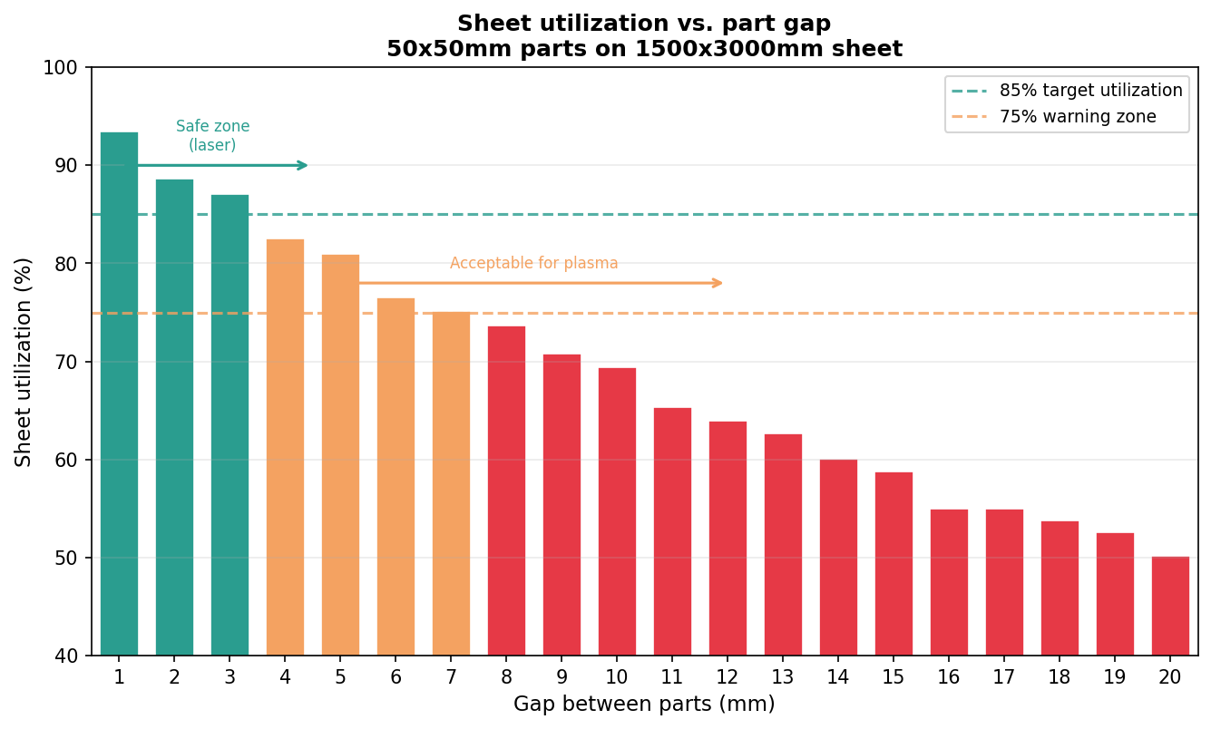
The effect is sharpest for small parts. A 50x50mm part is 2,500mm² and a 5mm gap around it adds roughly 500mm² of unusable space per part - 20% overhead. The same 5mm gap around a 300x400mm panel adds only 3% overhead. This is why small-part jobs are the highest-leverage place to audit your gap settings.
The cost numbers from the opening example scale predictably. A shop cutting 50x50mm parts at 10mm gaps and running 10,000 per month uses 8 sheets. Dropping to 2mm gaps brings that to 7 sheets. One sheet per month at $45 each is $540 per year for one part type. A shop cutting 30 different small part types with the same misconfigured gap is leaving $10,000–$15,000 per year on the table in material alone, before labor is counted.
When to use a larger gap deliberately
Minimum gaps set a floor, not an optimum. Three situations call for wider spacing than the table above:
Thin warping-prone material. Aluminum under 2mm and stainless under 1.5mm can develop measurable distortion from the radiated heat of adjacent cuts even when the HAZ itself is small. Adding 50–100% to the gap, combined with a cut sequence that avoids returning to adjacent areas while they’re still warm, reduces scrap from this.
Thick plasma plate. On plate above 12mm with standard plasma, heat input per pierce is substantial. The 25mm gap on 20mm plate in the table above feels excessive until the first time you try to cut 10mm away and get undercut edges from thermal runaway in the material web between parts.
Part retrieval by hand. If operators are lifting parts out by hand rather than running an automated sort, a slightly wider gap creates better finger clearance. This adds a handling constraint on top of the cutting constraint.
Choosing the right gap
This decision tree covers the majority of nesting configurations:
flowchart TD
    A[What is your cutting process?] --> B[Fiber laser]
    A --> C[CO2 laser]
    A --> D[Plasma]
    B --> E{Material thickness}
    E -- under 6mm --> F[Start at 2mm]
    E -- 6mm to 15mm --> G[Start at 3mm]
    E -- over 15mm --> H[Start at 4mm]
    C --> I{Material thickness}
    I -- under 6mm --> J[Start at 3mm]
    I -- over 6mm --> K[Start at 4–5mm]
    D --> L{HD or standard?}
    L -- HD plasma --> M[Start at 5–8mm by thickness]
    L -- Standard plasma --> N[Start at 8–15mm by thickness]
    F --> O{Aluminum or stainless under 3mm?}
    G --> O
    O -- Yes --> P[Add 50% to gap]
    O -- No --> Q[Run a test sheet at this gap]
    P --> Q
    Q --> R{Edge quality OK, no distortion?}
    R -- Yes --> S[Use this gap]
    R -- No --> T[Increase gap by 1mm, retest]
    T --> R
The test sheet step matters. Process documentation gives starting points, but the right gap for your specific machine, consumable condition, and material grade only comes from physical testing.
Setting part spacing in nesting software
In Lapas, the gap between parts is set in the nesting configuration before you run the engine. It applies uniformly to all parts in the job. The value you enter is the edge-to-edge clearance, not center-to-center, which is the standard convention in nesting software.
A few practical notes on using this setting:
Set the gap to your cutting-process minimum, not a round number picked for convenience. The difference between 3mm and 10mm on a small-part job is measurable in parts per sheet. If you’re running common line cutting, the gap setting becomes irrelevant for shared edges since those edges are eliminated - but it still governs non-shared contours.
For mixed-thickness jobs nested on the same sheet, use the gap appropriate for the thickest material if they’re from the same process. Alternatively, nest each thickness group separately and combine the resulting programs at the machine.
If your utilization feels low despite good part shapes and rotation freedom, the gap setting is the first thing to check. A quick audit: open your last three jobs, note the gap setting used, compare it against the process minimums in the table above. If your setting is more than 2x the minimum for your process, you’re leaving material on the sheet.
For more on how utilization benchmarks translate to cost, see material utilization rate benchmarks and material waste cost calculator.
The other setting: part rotation
Spacing decides how close parts sit. Rotation decides how they are turned before they are placed. They are the two settings that between them determine how tight a nest can get, so they are covered together here.
What rotation settings mean in practice
Most nesting software offers some combination of these modes:
| Setting | What it allows | Best for |
|---|---|---|
| No rotation | Parts stay in their original file orientation | Grain-critical materials, parts with directional features |
| 180° only | Parts can be flipped end-to-end | Symmetric parts where only mirroring matters |
| 90° steps (0/90/180/270) | Full orthogonal rotation | Most laser and plasma jobs |
| Custom step (e.g., 15°, 45°) | Rotation at fixed intervals | Angled parts, trapezoidal shapes |
| Free rotation | Any angle, continuous | Organic shapes, gaskets, freeform profiles |
The setting that produces the best utilization is almost always free rotation. The setting that produces the fastest computation is no rotation. The practical sweet spot for most shops is 90° steps, because it unlocks most of the orientation benefit at a fraction of the computation cost.
The numbers: utilization by aspect ratio
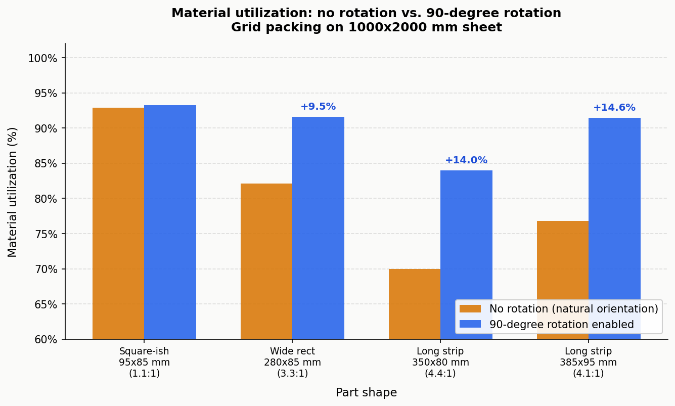
I ran a grid-packing simulation on a 1000×2000 mm sheet across four representative part types to show how much rotation actually changes material utilization. “No rotation” means the part is placed in its natural landscape orientation (as it comes out of the CAD file). “With rotation” means the optimizer can also try the part rotated 90°.
| Part | Size | No rotation | 90° rotation | Gain |
|---|---|---|---|---|
| Square-ish | 95×85 mm (1.1:1) | 92.9% | 93.3% | +0.4% |
| Wide rectangle | 280×85 mm (3.3:1) | 82.1% | 91.6% | +9.5% |
| Long strip | 350×80 mm (4.4:1) | 70.0% | 84.0% | +14.0% |
| Long strip | 385×95 mm (4.1:1) | 76.8% | 91.4% | +14.6% |
These are exact calculations for a uniform grid-packing arrangement, not estimates. The near-square part (95×85) is essentially the same in either orientation. The long strips improve by 9-15 percentage points simply because landscape orientation strands wide wasted columns at the sheet edge, while portrait orientation fills the sheet more evenly.
For irregular polygons, the gains from going beyond 90° rotation (to free rotation) are documented in research on polygon nesting algorithms. Burke et al. (2007), European Journal of Operational Research, showed that rotation constraints are the primary variable affecting utilization in irregular shape nesting - more so than algorithm choice. For concave parts with interlockable geometries, free rotation adds another 5-15% over fixed-angle rotation.
For rectangular parts, 90° rotation already achieves the optimal orientation, so free rotation offers no additional gain.
When to restrict rotation
Enabling full rotation on every job would be wrong. There are three legitimate reasons to restrict it.
Grain direction in sheet metal. Rolled steel and aluminium have mechanical properties that vary with the rolling direction. Parts with bend lines should be oriented so the bend runs perpendicular to the grain - this reduces cracking risk and allows tighter bend radii. A 3 mm stainless bracket that tolerates a 5 mm bend radius perpendicular to grain may crack at the same radius if bent parallel to grain. When grain direction matters, lock parts to 0°/180° rotation only, so the grain relationship is preserved.
Visible grain in wood and decorative materials. Plywood face veneer, brushed aluminium panels, and anodised sheet often look wrong if some parts are rotated 90° relative to others. This is an aesthetic constraint, not a mechanical one, but it’s just as real for shops doing decorative work.
Asymmetric functional features. Parts with asymmetric hole patterns, text engravings, or directional surface finishes may need to stay in a specific orientation for downstream assembly to work. This case is actually rarer than operators think - most parts are symmetric enough that rotation doesn’t affect function - but it does come up.
Outside these three cases, restricting rotation is usually a mistake that costs material for no benefit.
Choosing your rotation setting
The decision tree below covers most situations:
flowchart TD
    A[Does this part have a bend line\nor grain-critical direction?] -->|Yes| B[Will bending fail if grain\ndirection changes?]
    A -->|No| C[Does the part have\nasymmetric features?]
    B -->|Yes| D[Use 0°/180° only.\nGrain direction locked.]
    B -->|No| E[90° steps are safe.\nTest a sample bend first.]
    C -->|Yes, text or\ndirectional finish| F[Use no rotation or\n0°/180° only.]
    C -->|No or uncertain| G[Is the part\nnear-square, below 1.5:1?]
    G -->|Yes| H[Any rotation setting.\nDifference is under 2%.]
    G -->|No, aspect ratio\nover 1.5:1| I[Is the part rectangular\nor convex?]
    I -->|Rectangular\nor convex| J[90° steps.\nFree rotation adds nothing.]
    I -->|Irregular, concave,\nor freeform| K[Free rotation.\nExpect 5–15% extra yield.]
Most laser-cut parts with no bend requirements fall into the J or K branch. The practical default for a laser cutting shop on mild steel, acrylic, or plywood is: 90° steps for rectangular and near-rectangular parts, free rotation for irregular profiles.
Free rotation vs. step rotation: the computation trade-off
Free rotation means the algorithm has to evaluate the part’s no-fit polygon (the region where it cannot be placed without overlapping other parts) at potentially thousands of angles per placement decision. For a complex irregular polygon, this is computationally heavy.
90° steps means only four orientations are evaluated. The nested result is computed significantly faster, and for most rectangular and near-rectangular parts, the utilization is identical to free rotation.
The practical guidance: start with 90° steps on your first run. If the utilization is below what you’d expect given your part shapes, switch to free rotation and compare. For simple parts, 90° steps and free rotation will produce the same result. For complex irregular shapes, free rotation will do better, and the extra computation time (typically 20-60 seconds on a modern machine) is worth it on expensive material.
Lapas shows the utilization percentage on every completed nest. If you’re running 90° steps and getting below 82% on a job that has non-rectangular parts, free rotation will almost always close that gap.
Three rules that cover 90% of jobs
Rule 1: Aspect ratio under 1.5:1 - rotation barely matters. Square-ish parts pack nearly the same in any orientation. Don’t overthink it; 90° steps is fine.
Rule 2: Aspect ratio over 3:1 - always check if rotation is enabled. Long strips, bars, and slats have the most to gain from orientation flexibility. The data above shows gains of 9-15% just from enabling 90° rotation on these parts.
Rule 3: Irregular shapes with concavities - use free rotation. When parts can interlock (L-shapes, brackets, T-profiles), free rotation allows the optimizer to find angles where they mesh tightly. Restricting to 90° steps on these parts leaves material on the table that free rotation can recover.
FAQ
What is the minimum gap between nested parts for laser cutting? For fiber laser, the practical minimum is 1.5–2mm for material under 6mm thick, increasing to 3–4mm for plate above 10mm. CO2 laser needs slightly more room, starting at 2–2.5mm for thin material. These figures come from lead-in geometry requirements and the very small heat-affected zone fiber and CO2 processes produce.
Why does plasma cutting need a larger gap between parts than laser? Plasma cutting generates a larger heat-affected zone and more thermal spread than fiber or CO2 laser. Hypertherm documents the HAZ for high-definition plasma at under 0.25mm, but the heat radiating into the surrounding material extends further and can distort parts if the gap is too small. Standard plasma, with a wider arc and more heat input, needs 8–15mm minimum on most thicknesses where laser can use 2–4mm.
Does a smaller gap always mean better utilization? Smaller gaps improve utilization up to the point where parts actually fit closer together. Below the process minimum, you don’t gain utilization - you gain quality problems. The gains are largest for small parts (under 100x100mm), where the gap overhead is large relative to the part area. For parts above 300x300mm, the gap effect on utilization is relatively minor, usually under 5% between 2mm and 10mm.
What gap should I use if I’m cutting aluminum? For aluminum under 3mm on a fiber laser, start at 3mm (50% above the standard 2mm recommendation) because aluminum conducts heat very efficiently, meaning thermal spread from adjacent cuts is faster than with mild steel. For aluminum above 3mm, the standard gap table applies. Plasma on aluminum requires extra spacing; standard plasma on 3mm aluminum typically runs at 10mm minimum to prevent edge distortion.
My nesting software doesn’t have a gap setting. How do I handle this? Some older or simplified nesting tools apply a fixed gap or derive it from the kerf value. If the software has a kerf input but no separate gap setting, you can add the desired clearance to the kerf value to force larger spacing - though this conflates two different parameters. Kerf compensation works by shrinking part outlines inward by half the kerf width; part spacing is the clearance between the resulting outlines. The two are related but distinct. If you can’t control them separately, moving to a nesting tool that exposes both settings is worth considering for any production volume where material cost matters.
Spacing trades material against heat and skeleton rigidity. Set it in Lapas and watch the sheet count move as you change it.