Micro-Joints in Laser Cutting: Sizing Rules and the Nesting Decisions That Replace Them
Micro-joint sizing rules for laser cutting by material type and thickness, with the cut sequence and nesting orientation strategies that reduce how many you need.
A laser head crash costs you the full sheet, the consumables, and whatever machine time was already logged. I talked to an operator last month who lost a 4-hour nest at hour 3. The cause: a 90mm x 120mm bracket that tipped up when the last profile cut freed it from the sheet. The head clipped it, the job stopped, and the entire sheet went to scrap.
That crash was preventable. Not with better luck, but with a micro-joint on the bracket and a different orientation in the nest. This post covers both: how to size micro-joints correctly by material and thickness, and how nesting decisions reduce how many you need in the first place.
What makes a part tip up during laser cutting
When a fiber laser completes a closed profile cut, the freed part rests on the cutting table slats. Slats on most fiber laser tables are spaced 50 to 75mm apart. If a part is narrow enough in any direction, it can pivot on a single slat edge, tilt up, and intersect the head’s next move.
Three factors drive the risk:
Part size. Any dimension under 150mm (6 inches) puts a part at tip-up risk on a typical table. Both dimensions under 100mm and the part almost certainly needs a joint on thin sheet, regardless of material.
Material thickness. Sheet under 8mm is light enough that the cutting gas jet pushes freed parts around. High-pressure nitrogen at 10–20 Bar, used for stainless and aluminum, creates more upward force than low-pressure oxygen processes. Thick plate stays down from its own weight.
Slat pitch and part geometry. A part with both dimensions smaller than the slat pitch has no guarantee of spanning two slats. On a 60mm pitch table, a 55mm square bracket can sit entirely within one slat gap and drop - or tip when the gas flow catches it. Even longer parts that span the slats can tip if their center of mass shifts when a slug (internal scrap) is freed before the outer profile.
The physics is simple geometry. Understanding it means you can look at a part in the nest and predict, before the job runs, whether it needs a joint.
What micro-joints are - and how they fail
A micro-joint (also called a micro-tab or bridge) is a deliberate gap in the profile cut - a thin strip of uncut material that holds the part to the skeleton sheet until you break it by hand or mallet after the job completes.
They prevent tip-ups. They also add post-processing time: every joint has to be broken and the witness mark ground or filed smooth before the part ships. That’s not free.
More importantly, they fail in two specific ways:
Too small: The laser beam consumes the bridge entirely during the cut. The part tips anyway, and you’ve added post-processing time for a joint that didn’t work. The minimum safe joint length is always greater than 2x your actual kerf width. A 0.2mm kerf means the joint must be at least 0.4mm, or the laser cuts straight through it.
Too large: The part is difficult to separate, leaves a thick witness mark that needs grinding, and on stainless or aluminum can crack unpredictably rather than snapping clean. More isn’t safer - it just shifts the problem downstream.
Micro-joint sizing guide by material and thickness
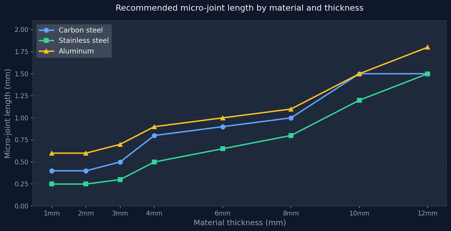
| Material | 1–3mm | 4–8mm | 10mm+ |
|---|---|---|---|
| Carbon steel | 0.3–0.5mm | 0.8–1.0mm | 1.5mm+ |
| Stainless steel | 0.2–0.3mm | 0.5–0.8mm | 1.2–1.5mm |
| Aluminum | 0.5–0.7mm | 0.9–1.1mm | 1.5mm+ |
Stainless takes the smallest joints because it work-hardens at the bridge point, making the connection brittle and easy to snap cleanly with little force. Use 3–4 small joints per part rather than 1–2 larger ones: multiple small joints distribute holding force without thickening any single contact point, which keeps the break clean and reduces grinding.
Aluminum needs slightly wider joints because residual heat from nitrogen-assist cutting partially melts tight bridges before the profile is complete. Going too small on aluminum creates a joint that has already been weakened by the time the next pass runs adjacent to it.
Carbon steel sits in the middle. On 2mm carbon steel, 0.4mm is a reliable starting point. Increase by 0.1–0.2mm if you’re seeing joints disappear; decrease by the same if you’re grinding for more than 30 seconds per part.
All of these numbers assume your actual kerf falls within the normal range for each thickness. Measure kerf periodically - lens wear, focus drift, and assist gas pressure all shift it. A joint sized for a 0.15mm kerf will fail if your actual kerf has crept to 0.25mm.
How many joints per part, and where to place them
The number of micro-joints needed depends on part shape:
Long, narrow parts (one dimension more than 5x the other): one joint on each long edge, placed at the midpoint. A 250mm x 40mm bracket wants to tip along its length axis. Two opposing midpoint joints lock it against that rotation.
Square-ish parts (aspect ratio under 3:1): two joints on opposite short edges are usually enough. The part can’t develop enough lever arm to tip against two joints on opposite sides.
Parts with large internal cutouts: The slug inside the cutout needs its own treatment. A large internal slug that tips before the outer profile is cut causes the same head crash as an external part. Either add a slug-destruct sequence (the controller cuts the slug into small pieces that fall through the slats) or use a joint to hold the slug in place until the outer profile completes.
Placement axis matters as much as count. Put joints at edges that cross the slat direction - not parallel to it. A joint aligned with a slat provides no rotational resistance. A joint crossing the slat axis locks the part against the exact rotation you’re preventing.
On thin sheet, the joint also keeps the part flat. High-pressure gas from adjacent cuts can lift a freed thin part even when it’s large enough not to tip. A single joint on thin sheet acts as a flat-down clamp - the sheet’s own weight holds the rest.
The nesting orientation that replaces joints for mid-sized parts
Here’s the decision that eliminates joints without adding post-processing: rotate the part in the nest so its longest dimension crosses the slats rather than running parallel to them.
A 200mm x 80mm plate bracket, nested with its 200mm side running perpendicular to the slats, spans 3–4 slat gaps. It will not tip. The same bracket, nested with the 80mm side parallel to the slats, may only contact 1–2 slat points and is genuinely at risk on thin material.
Part rotation settings in nesting software control this. If your operator already restricts rotation for grain direction or material anisotropy, they’re already making orientation decisions that affect tip-up risk. Adding slat direction as a consideration costs nothing - it’s the same decision, applied for a different reason.
Parts that need joints regardless of orientation: anything with both dimensions under 100mm. No rotation will make a 60mm x 40mm tab safe on 2mm sheet without a joint. The math doesn’t support it - the part fits within one or two slat spans no matter how you rotate it.
For everything in between - parts where one dimension is above 150mm and the other is between 80 and 150mm - orientation is the first thing to check before adding joints. Rotate across the slats and test. You may eliminate the joint entirely and save 30 seconds of post-processing per part.
Part spacing settings also affect how much skeleton remains between parts, which affects skeleton rigidity. A skeleton that bows mid-job lifts adjacent parts off the slats even before they’re freed. Keep spacing at or above the material thickness to maintain enough skeleton integrity to support the job through completion.
Cut sequence: inner before outer, and jump patterns for thin sheet
Micro-joints address part retention after cutting. Cut sequence addresses thermal distortion while the job is running - and distortion can lift parts off the slats even before they’re freed.
Research by Petunin, Polyshuk, Chentsov, Ukolov, and Krotov (2019) modeled heat conduction during CNC thermal cutting and found that cutting sequence - the order in which nested parts are processed - determines cumulative sheet temperature at each new pierce point. Their “Sheet Hardness Rule” heuristic automatically sequences parts to minimize localized heat buildup. (“The thermal deformation reducing in sheet metal at manufacturing parts by CNC cutting machines,” IOP Conference Series: Materials Science and Engineering, 613, 012041, DOI: 10.1088/1757-899X/613/1/012041.)
When CAM software doesn’t automate this, operators apply three rules manually:
Inner before outer. Cut all internal holes and features before the outer profile of each part. Once the outer perimeter is cut, the freed part can no longer support the surrounding skeleton material. Cutting internal features last means they’re processed in a sheet that has already been partially destabilized. Process internals while the sheet is still intact.
Small before large. Cut small parts first, starting from one corner of the sheet. Small parts removed from the edges don’t destabilize the remaining material. Large parts cut from the center early leave long unsupported spans that can bow under gas pressure, lifting surrounding small parts off the slats.
Jump cutting on thin sheet. Don’t cut adjacent parts in sequence. After completing one part, jump to a non-adjacent area before returning. This distributes heat across the sheet rather than building it up in one zone. On sheet under 2mm, cutting five adjacent parts in sequence creates measurable bow in the skeleton between parts 4 and 5 - enough to change pierce depth and affect cut quality.
Jump cutting adds travel distance for the cutting head, which adds a small amount of time. On thin sheet jobs where distortion is a real risk, that tradeoff is straightforward.
Decision guide for micro-joints in nesting
flowchart TD
    A[Part ready to nest] --> B{Any dimension under 150mm?}
    B -- No --> C[No micro-joint needed\nCheck cut sequence only]
    B -- Yes --> D{Both dimensions under 100mm?}
    D -- No --> E{Can part rotate to cross slat direction?}
    E -- Yes --> F[Rotate in nest\nRecheck tip-up risk at new orientation]
    F --> G{Still at risk after rotation?}
    G -- No --> K[No micro-joint needed]
    G -- Yes --> H[Add 1–2 micro-joints\nSee sizing table above]
    E -- No --> H
    D -- Yes --> I{Material thickness 8mm or above?}
    I -- Yes --> J[Part weight keeps it down\nVerify gas pressure is not excessive]
    I -- No --> L[Micro-joints required\nStainless: 3–4 small joints per part]
    C --> M[Inner-before-outer sequence\nJump pattern if sheet under 2mm]
    K --> M
    H --> M
    J --> M
    L --> M
FAQ
What is a micro-joint in laser cutting? A micro-joint is a small uncut strip of material - typically 0.2 to 1.5mm wide - left in a profile cut to keep the finished part attached to the skeleton sheet during cutting. It prevents the part from tipping up and hitting the laser head. The joint is broken by hand after the job completes.
What part size requires a micro-joint on a fiber laser? Parts with any dimension under 150mm (6 inches) are at tip-up risk on a typical table with 60–75mm slat spacing. Parts with both dimensions under 100mm almost always need at least one joint on sheet under 8mm thick. Thicker material is heavier and less likely to tip, but large internal slugs still need attention regardless of sheet thickness.
How do I size a micro-joint for 2mm stainless steel? Use 0.2–0.3mm joint length. Stainless work-hardens at the bridge, making it brittle and easy to snap clean. Use 3–4 joints per part rather than 1–2 larger ones. The minimum joint length is always greater than 2x your actual kerf width - measure kerf before setting joint size.
Why does my micro-joint disappear and the part still tip? Your joint length is smaller than 2x your kerf width. The laser beam consumes the bridge entirely during the profile cut. Measure your actual kerf (cut a test line and measure the slot), multiply by 2, and set joint length above that value. For 0.2mm kerf, minimum joint is 0.4mm.
Can changing the nesting orientation replace micro-joints? For parts where one dimension exceeds 150mm and the other is between 80 and 150mm, rotating the longer dimension perpendicular to the slat direction often eliminates the tip-up risk without any joint. For parts with both dimensions under 100mm, no rotation will compensate - joints are required on thin sheet regardless of orientation. Use part rotation settings to test orientations before committing to a joint strategy.
Does cut sequence affect part accuracy beyond just stability? Yes. Research on CNC thermal cutting shows that a poorly sequenced nest builds localized heat that causes measurable dimensional errors in cut parts, not just stability problems in the remaining skeleton. Inner-before-outer sequencing and jump patterns between parts reduce both instability and dimensional error from thermal stress. See the lead-in settings guide for related process parameters that affect entry quality on each pierce.
Joint strategy and part orientation are the same decision seen twice. Run the nest with rotation settings you control and compare tip-up risk across orientations.