Fiber Laser Nozzle Selection: Diameter, Standoff, and Wear Tolerance
How to choose nozzle diameter by thickness and assist gas, where to set standoff, and when to replace the nozzle before edge quality drops out of spec.
A shop in Poland called me about a 6 mm mild steel job that was suddenly producing slanted edges. Same DXF as last month, same gas, same pressure, same operator. The fix took five minutes once we walked through it: the nozzle had 38 cumulative cut hours on it, the orifice had bell-mouthed by about 0.2 mm, and the gas column was no longer concentric with the beam. A $35 part was throwing 200 brackets a day into the rework bin.
The nozzle is the cheapest part of a fiber laser and the one operators think about least. Get the diameter wrong for the assist gas, set the standoff outside a narrow window, or run it past the wear point and the cut goes sideways, sometimes literally. This post covers the three numbers that matter (diameter, standoff, replacement interval) and the data behind each one.
The short version
- Nozzle diameter scales with material thickness, but the rule depends on the gas. For oxygen on mild steel, diameter sits between 1.0 and 2.0 mm across the full thickness range. For nitrogen on stainless or aluminum, diameter scales at roughly 0.25 × thickness and reaches 3 to 5 mm on thick plate.
- Standoff (the gap from nozzle tip to sheet surface) wants to be between 0.5 and 1.5 mm for most fiber cutting, tighter for nitrogen, slightly looser for oxygen.
- A worn nozzle is the single most common cause of edge perpendicularity going out of ISO 9013 spec. Plan replacement by hours, not by appearance.
The rest of this post is the data that backs each of those numbers.
What the nozzle actually does
On a fiber laser cutting head, the nozzle has two jobs. It shapes and accelerates the assist gas into a tight column that flushes melt out of the kerf, and it sets the gas dynamics inside the cut. The laser beam passes through the orifice unobstructed. The nozzle does not focus the beam.
Two geometries dominate the market:
| Nozzle type | Construction | Typical use |
|---|---|---|
| Single (HK type) | One converging orifice, ~1.0 to 2.5 mm | Oxygen cutting, thin nitrogen work |
| Double (HD type) | Outer converging cone plus inner secondary orifice | Nitrogen cutting on medium and thick plate |
The double nozzle produces a more stable supersonic gas column at the high pressures (15 to 25 bar) needed for nitrogen cutting. Below about 4 mm of material, a single nozzle does the same job at lower consumable cost. Above 4 mm on nitrogen, the double nozzle holds dross down on the underside and keeps the kerf clear.
Nozzle diameter by thickness and gas
The diameter sets two things: how much gas mass flow the nozzle can pass per unit time, and how concentrated the gas column is at the cut zone. Oxygen cuts use small diameters because the gas chemistry does the heavy lifting; nitrogen cuts use large diameters because mechanical clearing of melt is the only mechanism.
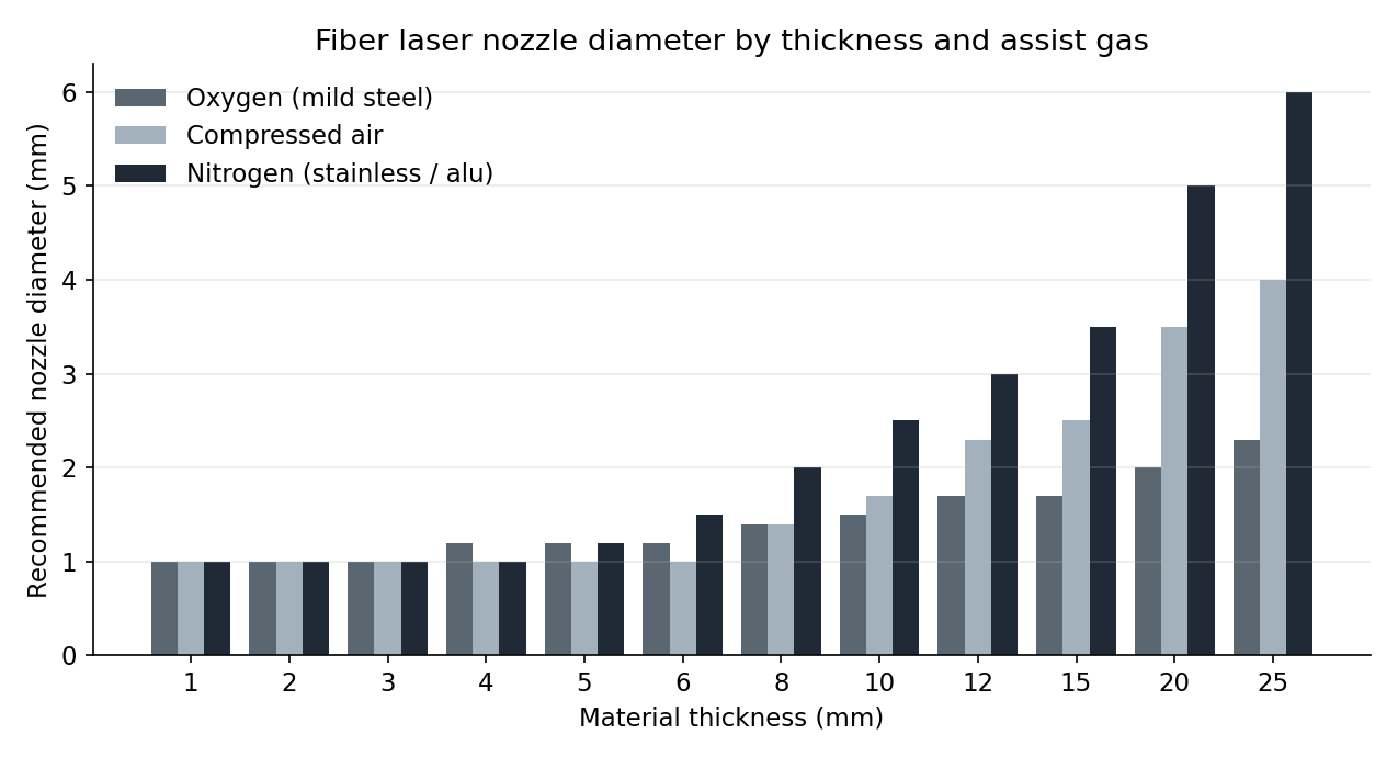
| Thickness | Oxygen (mild steel) | Compressed air | Nitrogen (stainless / aluminum) |
|---|---|---|---|
| 1 mm | 1.0 mm | 1.0 mm | 1.0 mm |
| 2 mm | 1.0 mm | 1.0 mm | 1.0 mm |
| 3 mm | 1.0 mm | 1.0 mm | 1.0 mm |
| 4 mm | 1.2 mm | 1.0 mm | 1.0 mm |
| 5 mm | 1.2 mm | 1.0 mm | 1.2 mm |
| 6 mm | 1.2 mm | 1.0 mm | 1.5 mm |
| 8 mm | 1.4 mm | 1.4 mm | 2.0 mm |
| 10 mm | 1.5 mm | 1.7 mm | 2.5 mm |
| 12 mm | 1.7 mm | 2.3 mm | 3.0 mm |
| 15 mm | 1.7 mm | 2.5 mm | 3.5 mm |
| 20 mm | 2.0 mm | 3.5 mm | 5.0 mm |
| 25 mm | 2.3 mm | 4.0 mm | 6.0 mm |
These are starting points pulled from Bystronic and Trumpf application manuals; treat them as a baseline and refine from cut samples. The nitrogen column especially is sensitive to small diameter changes: going from 2.0 mm to 2.3 mm on 8 mm stainless can cut dross by half if your pressure is borderline, because the larger orifice lets enough gas through to actually clear the kerf.
A common mistake is keeping a 1.5 mm nozzle on the machine when the program steps from 4 mm steel to 12 mm steel. The thin-sheet nozzle simply cannot pass enough mass flow on thick plate; the operator turns the pressure up to compensate, the bottle empties faster than expected, and the bottom edge still drosses. A double nozzle of the correct diameter would have solved it without burning gas.
Standoff distance
Standoff is the distance from the nozzle tip to the top surface of the sheet. On a capacitive height sensor it is the setpoint the head holds during cutting; on a mechanical follower it is the touch-off offset. The value matters because the gas column expands as it leaves the orifice, and the kerf only sees a useful pressure profile in a narrow downstream window.
| Gas | Typical standoff | Why |
|---|---|---|
| Oxygen | 1.0 to 1.5 mm | Lower pressure (1 to 6 bar) tolerates more spread |
| Compressed air | 0.8 to 1.2 mm | Mid-range; benefits from closer coupling |
| Nitrogen, single nozzle | 0.5 to 0.8 mm | High pressure column collapses quickly past 1 mm |
| Nitrogen, double nozzle | 0.7 to 1.0 mm | Secondary orifice extends the useful column length |
Too close (under 0.3 mm) and back-spatter from the kerf coats the nozzle, ceramic body, and protective window in seconds, blocking the orifice and frying optics. Too far (over 2 mm) and the gas column has expanded enough that pressure at the kerf falls below the threshold needed to clear melt; dross forms on the bottom edge and the cut may rough out before completing.
Walking the value in is straightforward: cut a 200 mm straight line at production parameters with standoff set to your machine’s default. If the cut is dross-free and the top edge is square, leave it alone. If you see dross, drop standoff by 0.2 mm and recut. If you see top-edge burning or back-spatter on the nozzle, raise standoff by 0.2 mm.
How a worn nozzle wrecks edge quality
The single number that tells you when to replace a nozzle is cut perpendicularity. I covered ISO 9013 ranges in Laser Cut Edge Quality and ISO 9013; the shorthand is that Range 2 is fabrication-grade (u below 0.15 mm on 6 mm steel), Range 3 is acceptable for most structural work, and Range 4 starts to look slanted to the eye.
A new nozzle holds Range 2 indefinitely on a tuned machine. As the orifice rim erodes from spatter, oxidation, and the occasional pierce splash, the gas column distorts off-axis and the kerf tilts. The chart below models perpendicularity over cumulative cut hours for three replacement habits.
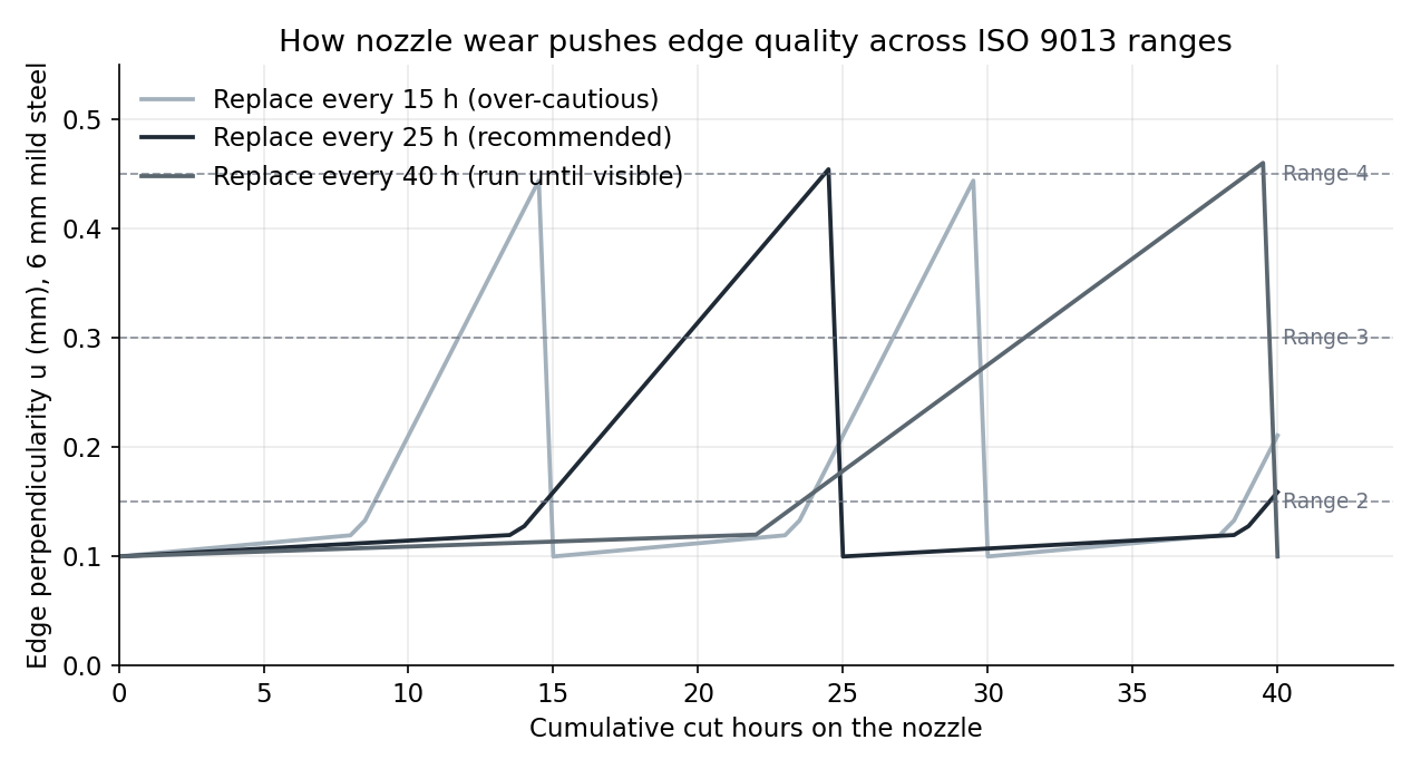
The 15-hour replacement curve never leaves Range 2. The 25-hour curve barely touches Range 3 at end-of-life. The 40-hour curve crosses into Range 4 around hour 30 and stays there for ten hours before a forced replacement. Those ten hours are where rework starts piling up.
The shop in Poland was on the 40-hour pattern by default: nozzles got changed when somebody noticed a problem. The problem only got noticed once it was already producing scrap.
What replacement actually costs
The consumable case for changing nozzles more often than feels comfortable is straightforward arithmetic. At 2000 cut hours per year (a single-shift production shop), here is what each strategy costs annually, including ceramic body and protective window:
| Replacement interval | Nozzle changes/year | Nozzles | Labor | Ceramic body | Window | Total consumables |
|---|---|---|---|---|---|---|
| 15 h (over-cautious) | 133 | $4,667 | $800 | $3,000 | $625 | $9,092 |
| 25 h (recommended) | 80 | $2,800 | $480 | $1,800 | $625 | $5,705 |
| 40 h (run to failure) | 50 | $1,750 | $300 | $1,125 | $625 | $3,800 |
Going from 40-hour to 25-hour replacement adds $1,905 per year in consumables and labor. The break-even is roughly 50 rework parts per year. A shop running 200 parts per shift across mixed thicknesses passes that in two days of bad cuts. The 25-hour pattern is almost always the cheaper one once scrap is in the model.
Assumptions: $35 per nozzle, $90 per ceramic body (lasts about four nozzles), $25 per protective window (replaced every 80 cut hours), 8 minutes labor per changeover at $45 per hour loaded rate.
A nozzle selection workflow
flowchart TD
    A[New job arrives] --> B{Material?}
    B -->|Mild steel, structural| C[Oxygen]
    B -->|Stainless or aluminum| D[Nitrogen]
    B -->|Mild steel, thin cosmetic| E[Air or nitrogen]
    C --> F{Thickness?}
    D --> G{Thickness?}
    E --> H[Single 1.0 to 1.2 mm]
    F -->|under 6 mm| I[Single 1.0 to 1.2 mm]
    F -->|6 to 15 mm| J[Single 1.2 to 1.7 mm]
    F -->|over 15 mm| K[Single 2.0 to 2.5 mm]
    G -->|under 4 mm| L[Single 1.0 to 1.2 mm]
    G -->|4 to 8 mm| M[Double 1.4 to 2.0 mm]
    G -->|over 8 mm| N[Double 2.5 to 5.0 mm]
    H --> O[Check standoff, cut sample]
    I --> O
    J --> O
    K --> O
    L --> O
    M --> O
    N --> O
    O --> P{Edge in spec?}
    P -->|Yes| Q[Log cut hours, run job]
    P -->|No, dross underneath| R[Drop standoff 0.2 mm, retry]
    P -->|No, slanted edge| S[Replace nozzle, recenter]
The two failure branches at the bottom are the recurring ones. Dross under the cut is almost always standoff or pressure, not the nozzle itself. A slanted edge with otherwise normal cut behavior is almost always nozzle wear or off-axis centering.
Centering: the one alignment check operators skip
A fresh nozzle does nothing if the beam is not concentric with the orifice. On most fiber heads, centering drifts gradually as the head heats up and cools down, as ceramics get replaced, and as the cover slide is exchanged. The check takes ninety seconds with a piece of tape over the nozzle and a low-power pulse.
Asymmetric burn pattern on the tape means the beam is hitting one side of the orifice. The gas column then exits the kerf at an angle, and the cut tilts toward the high-pressure side. On thin sheet you may not notice. On 6 mm steel and up, a 0.05 mm off-center beam can shift the bottom edge by 0.3 to 0.5 mm relative to the top.
Centering is the cheapest tune-up there is. Make it part of the nozzle change routine, not an annual service item.
How this connects to nesting
The nesting layout decides where the head starts each cut, how often it pierces, and how heat accumulates across the sheet. A worn nozzle amplifies every weakness in the cut order: more pierces on a tired nozzle means more spatter, more spatter means faster wear, and a poorly sequenced job catches up to the replacement schedule before the shift ends.
Two specific nesting choices reduce nozzle stress:
- Common-line cutting reduces total pierces. I covered the numbers in Common Line Cutting; the same logic applies here.
- Pierce-friendly lead-ins keep spatter away from the nozzle face. See Lead-In and Lead-Out Settings for CNC Cutting for the geometry rules.
Lapas applies both by default on the optimization runs, which is one of the reasons production shops see nozzle life extend by 15 to 25% after switching from manual nesting. The cause is mundane: fewer pierces, cleaner lead-ins, less spatter.
FAQ
Can I use one nozzle diameter for everything?
You can, and most low-volume shops do. The trade-off is that the compromise diameter undercuts speed on thick plate and overconsumes gas on thin sheet. For a shop that runs 3 mm steel one week and 12 mm the next, keeping two nozzle types staged saves more in gas than the nozzles cost. For a shop that runs 90% in a narrow thickness band, one nozzle is fine.
Why does my new nozzle still cut badly?
In order: centering, focus position, standoff, gas purity. A fresh nozzle that produces a bad cut is almost never defective. The most common cause is beam centering drift from the previous head event (a crash, a ceramic change, a thermal cycle). Run the tape test before assuming the nozzle is the problem.
How do I tell a worn nozzle from a damaged one?
Look at the orifice under magnification. Wear shows up as a bell-mouthed inner rim and a slightly enlarged diameter, both symmetric. Damage shows up as a notch, a dimple, or asymmetric melt around the rim, usually from a crash or a back-spatter event. Damaged nozzles get thrown away regardless of hours. Worn nozzles get logged and replaced on schedule.
Does nozzle diameter affect kerf width?
Indirectly. The kerf width is set by the beam diameter at the cut zone, not the orifice. But a too-small nozzle running undersupplied gas widens the heat-affected zone and produces a rougher, slightly wider kerf because melt re-solidifies on the cut walls. A correctly sized nozzle on adequate gas produces the narrowest, cleanest kerf the machine can deliver. The kerf compensation I covered in Kerf Compensation in Nesting Software assumes the nozzle is sized correctly.
Is single-use or refurbished worth it?
Refurbished nozzles re-machine the orifice on a worn nozzle body. The body itself is high-tolerance brass, and a good refurb is indistinguishable from new at about 40% of the cost. The risk is that the refurb shop’s tolerance is wider than the original; on thin gauge nitrogen work, that extra 0.05 mm of orifice variation can drift the gas column off the kerf centerline. For oxygen cutting on mild steel, refurb is generally fine. For nitrogen on stainless, stay with fresh.
Sources
- Bystronic AG. (2022). ByStar Fiber Application Handbook: Cutting Parameters and Consumables.
- Trumpf GmbH. (2021). TruLaser Series 5000 Operating Instructions, Section 7: Consumables.
- Steen, W. M., and Mazumder, J. (2010). Laser Material Processing (4th ed.). Springer.
- ISO 9013:2017. Thermal cutting - Classification of thermal cuts - Geometrical product specification and quality tolerances.