Laser Cut Edge Quality: How to Read ISO 9013 and Diagnose Common Defects
Diagnose dross, striations, burrs, and perpendicularity errors on laser cut edges using the ISO 9013 framework. Defect chart, root causes, and operator fixes.
A fabricator I work with sent me a photo of a stainless bracket last month. The cut edge was bright on the top half and ragged on the bottom, with stringy melt hanging off about half the perimeter. The shop owner had been arguing with his powder coater for two weeks about who was responsible for the rejected batch. My answer was neither of them. The edge in that photo was textbook ISO 9013 Range 4 on a part that needed Range 2, and the parameters that produced it were sitting in the machine controller in plain view: nitrogen pressure 8 bar when 14 was the recommended setting for that thickness.
Edge quality complaints almost always trace back to one of four parameters: focus position, gas pressure, cutting speed, or nozzle condition. The hard part is not fixing them. The hard part is reading the cut edge accurately enough to know which one is wrong. ISO 9013 gives you a vocabulary for that, and once you can name what you are looking at, the fix is usually fifteen minutes of test cuts on scrap.
What ISO 9013 Actually Measures
ISO 9013:2017 (“Thermal cutting — Classification of thermal cuts”) is the international standard for grading thermal cut edges, covering laser cuts from 0.5 to 40 mm, plasma from 1 to 150 mm, and oxyfuel from 3 to 300 mm. It defines two primary parameters, plus three secondary ones that operators reference informally:
Perpendicularity tolerance (u): how far the cut edge deviates from a true 90 degree angle to the sheet face, measured in millimeters. A perfectly square edge has u = 0. Real fiber laser cuts on 10 mm mild steel typically run u between 0.05 and 0.15 mm.
Mean height of profile (Rz5): the average peak-to-valley striation height over five sampling lengths on the cut face, measured in microns. This is the visible “drag line” texture on the cut edge. ISO 9013 uses Rz5 rather than the more common Ra because thermal cut surfaces have characteristic periodic striations that Ra under-reports.
The standard sorts both measurements into four quality ranges. Range 1 is the tightest tolerance, Range 4 is the loosest. The ranges are not absolute numbers, they are linear formulas that scale with material thickness, because thicker cuts inherently produce more taper and rougher edges:
| Range | Perpendicularity u (mm) | Surface roughness Rz5 (microns) |
|---|---|---|
| Range 1 | 0.05 + 0.003 × t | 10 + 0.6 × t |
| Range 2 | 0.15 + 0.007 × t | 40 + 0.8 × t |
| Range 3 | 0.4 + 0.01 × t | 70 + 1.2 × t |
| Range 4 | 0.8 + 0.02 × t | 110 + 1.8 × t |
Where t is the material thickness in mm. For a 10 mm plate, that means Range 1 perpendicularity is 0.08 mm and Range 1 roughness is 16 microns; Range 4 perpendicularity is 1.0 mm and Range 4 roughness is 128 microns.
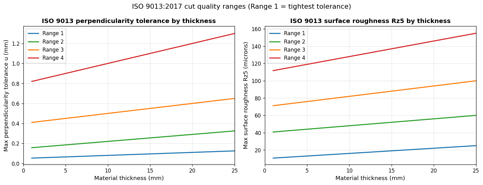
The standard requires a perpendicularity measurement and a roughness measurement, and the worse of the two determines the range. A cut that hits Range 1 on perpendicularity but only Range 3 on roughness is a Range 3 cut.
What Range Your Fiber Laser Should Hit
A well-tuned 6 kW fiber laser cutting mild steel with nitrogen produces these typical Rz5 values, measured from manufacturer cut quality guides published by Bystronic and TRUMPF:
| Thickness | Typical Rz5 (microns) | ISO 9013 range |
|---|---|---|
| 1 mm | 8 | Range 1 |
| 2 mm | 12 | Range 2 |
| 3 mm | 18 | Range 2 |
| 5 mm | 28 | Range 2 |
| 8 mm | 45 | Range 2 |
| 10 mm | 58 | Range 3 |
| 12 mm | 75 | Range 3 |
| 15 mm | 95 | Range 4 |
Two patterns are worth naming. First, only the thinnest cuts reliably hit Range 1; below 2 mm you should expect Range 1, above that, Range 2 is the practical ceiling on a production machine. Second, thicker cuts degrade fast. Going from 10 mm to 15 mm pushes Rz5 from 58 to 95 microns, which crosses two ISO 9013 boundaries. Customers spec’ing “smooth” 15 mm cut edges on fiber laser without specifying Range 3 or Range 4 are spec’ing something most production shops cannot deliver consistently.
For powder coating and weld-prep work, Range 3 is usually acceptable. For visible architectural parts that ship as-cut, Range 2 is typically the lower bound. For sealing surfaces or precision-fit assemblies, Range 1 is the target, which usually requires either thinner material, a slower second pass, or a finishing operation downstream.
The Defect Vocabulary
When you pick up a cut part and run a finger across the edge, you are looking for one or more of seven defects. Each one has a specific signature and a specific root cause.
| Defect | What you see | Primary cause | First fix to try |
|---|---|---|---|
| Dross on bottom edge | Re-solidified metal hanging off the underside, often beard-like | Speed too high or gas pressure too low | Drop speed 10%, then raise N2 pressure 2 bar |
| Hard dross, welded to edge | Sharp solid metal you cannot scrape off | Focus too low, melt re-attaching | Raise focus position by 0.5 mm |
| Soft dross, easily knocked off | Loose granular slag | Gas pressure marginal | Raise pressure 1-2 bar |
| Striations, deep and irregular | Visible vertical drag lines, especially mid-thickness down | Speed too high for the power | Reduce speed 15% as first step |
| Burrs, sharp top edge | Raised metal lip at the top of the cut | Focus too high, beam burning top edge | Lower focus 0.3-0.5 mm |
| Edge taper, top wider than bottom | Cut wider at entry than exit | Focus position above sheet, or beam divergence | Set focus to mid-thickness or slightly below |
| Top edge rounding / melt | Top corner has rolled-off appearance | Excess power for the speed | Drop power 10% or raise speed |
| Pitting on stainless | Small craters or oxide spots | Low N2 purity or contaminated gas | Check supply, target 99.95% minimum |
| Color tinting on stainless | Straw, blue, or black edge | Oxygen contamination in N2 stream | Check hose seals; replace filter |
The pattern across this table is that nearly every defect has two or three possible causes, and the differential diagnosis comes down to where on the edge you see the defect. Dross at the bottom is a different problem than dross stuck to the side. Striations near the top are different from striations near the bottom.
A Diagnostic Flow That Actually Works
When a defect appears, the question is which parameter to change first. The wrong order wastes test cuts and material. This is the sequence I run in my own diagnostic checks:
flowchart TD
    A[Defect appears on cut edge] --> B{Where on the edge?}
    B -->|Bottom: dross or melt| C{Hard or soft dross?}
    B -->|Top: burrs or rolled corner| D[Lower focus position 0.3-0.5 mm]
    B -->|Mid-edge: deep striations| E[Reduce cutting speed 10-15%]
    B -->|Full edge: tint or pitting| F[Check gas supply and purity]
    C -->|Soft, knocks off| G[Raise N2 pressure 1-2 bar]
    C -->|Hard, welded| H[Raise focus 0.5 mm, then drop speed 10%]
    D --> I{Defect resolved?}
    E --> I
    F --> I
    G --> I
    H --> I
    I -->|Yes| J[Lock parameters in cut library]
    I -->|No| K[Inspect nozzle: damaged, off-center, or worn?]
    K -->|Yes| L[Replace nozzle, recheck centering]
    K -->|No| M[Run beam alignment and lens check]
The order matters. Operators commonly start by changing the most visible parameter (usually power), but in 8 out of 10 cut quality calls I see, the actual fix is focus position or nozzle condition. The MDPI 2023 study by Pamcek et al., “Multi-Objective Optimization of Fiber Laser Cutting of Stainless-Steel Plates Using Taguchi-Based Grey Relational Analysis,” confirmed this experimentally: focus position and cutting speed had the largest effect on surface roughness, while power had the smallest effect within the operating window for 3 mm stainless.
The Four Parameters That Actually Move the Edge
Focus position controls where the beam waist sits relative to the sheet. For nitrogen cutting, the rule of thumb is focus 1/3 to 2/3 of the way through the material from the top surface. Too high and the kerf widens at the top, producing top burrs and a wedge-shaped cut. Too low and the bottom edge struggles to expel melt, producing hard dross.
Gas pressure determines whether the kerf gets cleared. For nitrogen on stainless, pressure scales with thickness. On 1 mm you can run 10 bar; on 6 mm you need 16; on 10 mm and above you are typically at 20-25 bar. Under-pressure shows as dross, soft and easily knocked off but covering the bottom edge.
Cutting speed sets the heat input per millimeter of cut. Too fast and the laser does not fully penetrate, leaving incomplete cuts or jagged striations near the bottom. Too slow and the kerf overheats, producing wide cuts, top edge rounding, and burning on the lead-in stub.
Nozzle condition is the silent killer. A nozzle that is off-center by 0.1 mm produces directional asymmetry: clean cuts in one direction, dross-laden cuts in another. A worn nozzle bore expands the gas cone and drops effective pressure at the kerf, producing all the symptoms of low gas pressure even when the regulator reads correctly. I recommend nozzle inspection at the start of every shift on production machines.
How Nesting Connects to Edge Quality
Nesting decisions can either help or aggravate edge quality issues, and shops rarely think about this connection.
Lead-in placement on the wrong side of a part puts the pierce stub on a visible edge. If the visible edge has any tolerance for a small notch (usually 0.5-1 mm), placing the lead-in there is fine. Otherwise, lead-ins should land on scrap-side edges or on cut features that will be removed downstream. Lead-in and lead-out settings covers this in detail.
Micro-joints hold parts in place during cutting to prevent tipping, but they leave a small witness mark on the edge. Placing the joint on the same scrap-side edge as the lead-in concentrates all the cosmetic damage in one place, which is usually preferable to scattering small marks around the perimeter.
Cut sequence affects edge quality indirectly through thermal distortion. A sheet that bows during cutting changes the effective focus position part-to-part, which can push otherwise-acceptable parameters into the wrong ISO 9013 range halfway through the job. Symptoms look identical to a focus drift on the machine, but the root cause is the nesting cut order.
In Lapas, part spacing and rotation are set per job, so when you find a cut quality issue that traces back to the nest, you can target the nesting fix instead of just dialing the machine. Lead-in placement, micro-joints and cut sequence beyond holes-first stay in your CAM.
When to Recut and When to Accept
The most expensive cut quality mistake is recutting parts that would have shipped fine, and the second most expensive is shipping parts that needed a recut. The ISO 9013 framework gives you a sortable rule:
| Part destination | Minimum recommended ISO 9013 range |
|---|---|
| Internal weldments, prep before weld | Range 4 acceptable |
| Powder coated structural parts | Range 3 |
| Visible architectural, painted | Range 2 |
| Cosmetic, as-cut, no finishing | Range 1 or Range 2 |
| Sealing surfaces, precision-fit | Range 1, often requires finishing |
The honest version of this table is that most production shops cannot reliably hit Range 1 above 3 mm on fiber laser, and they should price jobs accordingly. If a customer specifies Range 1 on 10 mm plate without a secondary finishing operation, the conversation needs to happen before quoting, not after delivery.
FAQ
What ISO 9013 range does a typical fiber laser produce? On well-tuned 6 kW fiber laser with nitrogen, mild steel below 8 mm typically hits Range 2 on both perpendicularity and roughness. Above 10 mm, expect Range 3. Above 15 mm, Range 4 is common.
How do I measure perpendicularity in the shop without lab equipment? A machinist square and feeler gauges work for thick cuts. Place the square against the cut edge on the sheet face, push the part against the square, and use feeler gauges to measure the gap at the bottom edge. For thinner cuts under 5 mm, an optical comparator or a vision-based measuring system is more practical.
Why does my cut quality vary across the sheet on the same parameters? Three usual causes: sheet flatness (warped material puts the focus in the wrong place), thermal distortion accumulating during the job, or nozzle off-center which produces directional asymmetry. Cut a small test part in each corner of a sheet and compare. If the variation is corner-to-corner, suspect distortion or flatness. If it is direction-of-cut variation on a single part, suspect the nozzle.
Is hard dross a sign the machine needs service? Not usually. Hard dross most commonly indicates focus position is too low or cutting speed is too high for the gas pressure available. If you have ruled out parameters and the nozzle, then beam quality (M-squared) or lens condition is the next check, and those do need service.
Does cut quality matter for parts that get welded over the cut edge anyway? Less than people think. ISO 9013 Range 4 cut edges weld fine after prep, and Range 3 typically welds without prep on mild steel. The risk is dross detaching during welding and contaminating the joint. For weld prep, focus on consistent dross removal rather than achieving a low Rz5 number.
Sources:
- ISO 9013:2017 - Thermal cutting — Classification of thermal cuts — Geometrical product specification and quality tolerances. International Organization for Standardization, 2017.
- Pamcek, A., et al. “Multi-Objective Optimization of Fiber Laser Cutting of Stainless-Steel Plates Using Taguchi-Based Grey Relational Analysis.” Metals, MDPI, 2023.
- Bystronic AG, Cut Quality Application Guide for Fiber Laser, 2024.
Edge quality and part spacing interact: too little clearance and heat from the adjacent cut shows up in the edge. Lapas laser cutting nesting exposes spacing directly.