Plasma Cutting Small Holes: The 1.5× Rule, Hole Taper, and When to Drill Instead
Why plasma struggles with small holes, the 1.5× thickness rule by plasma class, hole taper data, and a cost comparison for cutting vs drilling secondary.
A fabricator I work with sent me photos of a batch he was about to scrap. 100 brackets, each with six 8 mm bolt holes in 10 mm mild steel. The holes measured right at the top and 0.4 mm undersize at the bottom. Bolts went in straight from above and bound halfway through. He thought the machine was out of square. The machine was within spec. The job was the problem: he was asking a standard plasma to cut a hole 0.8× the material thickness, well under the 1.5× rule that every plasma manufacturer publishes for a reason.
Short answer: plasma cannot reliably cut a round, parallel-walled hole below roughly 1.5× the plate thickness on a conventional system, or below 1.0× on high-definition plasma. Below those ratios you get taper, dross, and out-of-round geometry that downstream operations cannot fix cheaply. The right move is usually to cut oversize and drill to size, or cut a small pilot and drill it open. Whether that is faster than fighting taper depends on hole count and thickness. The numbers below let you decide on the job, not on a hunch.
Why Plasma Struggles With Small Holes
A plasma arc is a column of ionized gas about 1–3 mm wide at the work surface, with a kerf that widens slightly toward the bottom. On a long straight cut the geometry is invisible: dwell along each section of edge lets the arc stabilize and the kerf taper stays uniform. On a small hole, three things stack against you.
First, the cut is mostly transient. The arc spends most of its time accelerating, decelerating, or piercing. There is not enough straight-line cutting for the arc to reach steady state, so the kerf shape varies around the perimeter.
Second, the lead-in occupies a meaningful fraction of the circumference. A 6 mm hole has 18.8 mm of perimeter; even a 2 mm lead-in is 10% of it, and that section is where pierce blow-back contaminates the edge.
Third, kerf taper is amplified by feed rate. The 2024 study by Tuladhar et al. in the Journal of Mechanical Science and Technology used ANOVA to characterize plasma kerf geometry and found cutting speed had the largest single effect on taper angle, with current second and standoff third. Higher feed rates open the top kerf and narrow the bottom, which is the same failure mode the bracket job above showed. Hypertherm’s published guidance is that holes under one inch should be cut at 60% of nominal feed rate to keep taper inside spec.
The Ratios That Actually Work
Different plasma classes hit different minimum hole diameters. These numbers come from manufacturer-published specs, not estimates.
| Plasma system class | Min hole : thickness | Source |
|---|---|---|
| Conventional / oxy-fuel | 2.0 : 1 | Swift-Cut hole tolerance guide |
| Industry rule of thumb | 1.5 : 1 | Kjellberg, Hypertherm small-hole definition |
| High-definition plasma | 1.0 : 1 | Typical HD systems on mild steel |
| Hypertherm True Hole | 0.75 : 1 | Hypertherm SureCut extended envelope |
| Kjellberg Contour Cut (Q-series) | 0.6 : 1 | Demonstrated 6 mm hole in 10 mm plate |
Kjellberg states directly that “a rule of thumb says that the smallest possible hole has a diameter which is approximately one and a half times the plate thickness.” Hypertherm formally defines a “small hole” as any hole with diameter less than 1.5× the material thickness and treats those holes with different feed and current parameters in their CAM packages. Voortman puts the practical economic line at 2× thickness: below that ratio drilling secondary is usually faster than fighting taper.
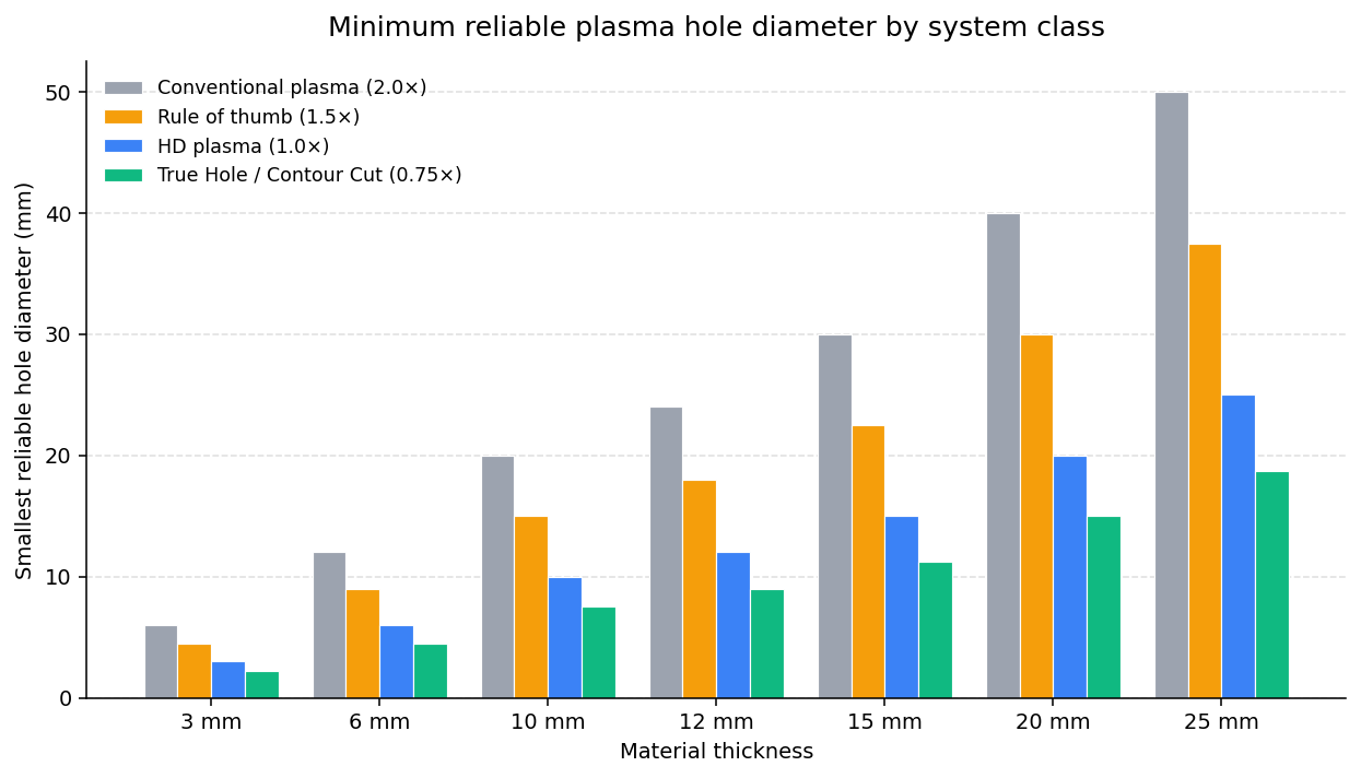
A 10 mm plate cannot reliably take a hole smaller than 15 to 20 mm on conventional plasma. An HD system takes the same plate down to 10 mm holes. True Hole or Contour Cut pushes to 7.5 to 8 mm, and Kjellberg has demonstrated 6 mm holes in 10 mm plate on the Q-series. Below those thresholds, expect rework.
What “Out of Spec” Actually Looks Like
ISO 9013:2017 grades thermal cut edges using perpendicularity tolerance u and surface roughness Rz5, both scaled by material thickness. Plasma cuts typically land in ISO 9013 Range 2 to Range 4. On small holes the perpendicularity degrades fast because the arc never reaches steady state.
Kjellberg’s published HiFocus tolerance on a hole in 10 mm mild steel is ±0.2 mm top-to-bottom edge deviation, roughly 1.1 degrees of kerf wall taper. That is the best case for HD plasma at the small end of its spec. Conventional plasma at the same ratio can easily produce 0.5 to 1.0 mm deviation, or 3 to 6 degrees of taper, enough to make a tapped hole unusable and an unthreaded bolt-pass hole bind.
Practical shop test: run a pin gauge through a small hole sample from both sides. If the same gauge falls through from one side but not the other, the hole has positive taper. The difference between the two pin sizes is roughly your top-to-bottom kerf delta. If it exceeds 5% of the hole diameter, the hole will reject any close-tolerance assembly downstream.
Cut or Drill: The Cost Calculation
Worked numbers for 8 mm holes in 10 mm mild steel:
| Method | Time per hole (s) | Cost per hole ($) | Quality risk |
|---|---|---|---|
| Conventional plasma, 60% feed | 3.6 | 0.20 | High taper, likely reject |
| HD plasma, 60% feed | 2.3 | 0.16 | Borderline, slow feed mandatory |
| True Hole, nominal feed | 1.8 | 0.14 | In spec |
| CNC drill, post-process | 12.0 | 0.25 | Cylindrical, in tolerance |
Assumes $100/hour loaded machine rate for plasma, $60/hour for CNC drill, $15/hour consumables, $0.083 per pierce (Hypertherm qualifies consumables to 300 pierces per set at $25), and $0.05/hole bit amortization on the drill.
On True Hole, cutting is faster and cheaper with no quality risk. On conventional plasma, drilling secondary costs 25% more per hole but eliminates the reject risk: $5 extra across 100 holes to save what would otherwise be a $200 batch of scrapped brackets. The numbers swing further toward drilling as hole count per part rises, because each pierce eats consumable life.
| Pierces per part | Total pierces, 100 parts | Consumable sets | Consumable cost ($) |
|---|---|---|---|
| 1 | 100 | 0.33 | 8 |
| 5 | 500 | 1.67 | 42 |
| 10 | 1,000 | 3.33 | 83 |
| 20 | 2,000 | 6.67 | 167 |
| 50 | 5,000 | 16.67 | 417 |
For parts that are mostly holes, drilling is dramatically cheaper at the consumable line, even before you count reject rates.
There is also the nitriding trap. Operators on PlasmaSpider and Practical Machinist describe plasma-cut edges as resistant to drilling because the molten edge hardens in the nitrogen-rich atmosphere. The hardened layer is typically 0.1 to 0.3 mm deep. If the workflow plans to drill after plasma, cut the pilot well undersize so the drill removes the entire nitrided edge in one pass.
Nesting Decisions That Affect Hole Quality
Three nesting decisions matter for small-hole quality, and shops rarely think about them.
Lead-in placement. A lead-in inside the hole consumes circumference and dumps pierce blow-back onto the edge. The lead-in should be as short as the controller allows, usually 1 to 2 mm, and tangent to the hole rather than a perpendicular dive.
Sequence and thermal accumulation. Cutting all holes in a part consecutively pumps heat into a small area, warping the sheet locally and changing the effective focus height for the next pierce. The cut sequence for small-hole-heavy parts should interleave holes with longer cuts to let the plate cool. Symptoms of getting this wrong look identical to consumable wear: gradually increasing taper across a job. The fix is sequencing, not new consumables.
Hole-edge distance to part boundary. A small hole within one material thickness of an outer cut path will show asymmetric taper, because arc gas pressure differs on the side facing solid material versus the side facing the kerf. Maintain at least 1.5× thickness between hole edge and part edge if roundness matters.
flowchart TD
    A[Hole diameter and thickness known] --> B{Hole : thickness ratio}
    B -->|"≥ 2.0×"| C[Cut on plasma, in spec]
    B -->|"1.5×–2.0×"| D{HD or True Hole available?}
    B -->|"1.0×–1.5×"| E{HD or True Hole available?}
    B -->|"< 1.0×"| F{True Hole / Contour Cut available?}
    D -->|Yes| C
    D -->|No| G[Cut oversize, drill to size]
    E -->|HD yes| C
    E -->|True Hole yes| C
    E -->|Neither| G
    F -->|Yes| C
    F -->|No| H[Plasma pilot, drill to size, or drill only]
In Lapas, part spacing and the sheet border are set per job, and holes are cut before outlines in its exports, so when you find a hole-quality issue that traces back to the nest you can target the nesting fix instead of just slowing the feed and hoping. Lead-in length for your table stays in your CAM.
FAQ
Why are my plasma holes tapered even when the parameters are right? Taper on small holes is intrinsic to the kerf geometry, not a parameter error. Below the 1.5× ratio on conventional plasma, the arc cannot reach steady state around the circumference and the kerf opens at the top. Slowing the feed helps but does not eliminate it. The real fix is a higher-class plasma system or drilling.
Can I just slow the feed rate and cut tiny holes? You can drop to 60% of nominal, which is Hypertherm’s published spec for holes under one inch. Below the 1× ratio on HD plasma or 0.75× on True Hole, slowing further produces overheating and dross rather than improvement. The diameter ratio is a hard floor, not a feed-rate problem.
Do I need True Hole, or is HD plasma enough? For mild steel holes down to 1× thickness, standard HD plasma is enough. Between 0.75× and 1×, True Hole or Kjellberg Contour Cut delivers a measurable improvement. Below 0.75×, no plasma system is competitive with drilling.
Why are my plasma-cut holes hard to drill open afterward? The cut edge nitrides during the cut, a chemical hardening from the molten edge meeting nitrogen in the cutting atmosphere. The hardened layer is typically 0.1 to 0.3 mm deep. Use cobalt or carbide bits; HSS dulls fast. Cut the pilot well undersize so the drill removes the entire nitrided edge in one pass.
Does plasma small-hole quality affect threaded holes too? Yes, and worse. Tapping into a tapered hole produces inconsistent thread engagement: full at the bottom and partial at the top, or vice versa, depending on tap geometry. Threaded holes on plasma should always be cut oversize and tapped after, never tapped directly into a plasma-cut hole.
Sources:
- ISO 9013:2017, Thermal cutting Classification of thermal cuts. International Organization for Standardization, 2017.
- Tuladhar, U., Ahn, S.H., Cho, D.W., et al. “Experimental investigation of plasma arc cutting process to evaluate the characteristics of kerf geometry using ANOVA.” Journal of Mechanical Science and Technology, vol. 38, 2024, pp. 3641–3655.
- Hypertherm: How can I cut better holes?, Hypertherm technical FAQ.
- Hypertherm True Hole technology overview, Hypertherm SureCut documentation.
- Kjellberg Finsterwalde: Small holes in plasma cutting, Kjellberg Plasma technical reference.
- Swift-Cut: Hole tolerances for plasma cutting, 2020.
- Voortman: Drilling versus cutting holes, Voortman Steel Machinery knowledge base.
Hole quality is a process problem, but plate consumption is a nesting one. Plasma cutting nesting in Lapas lets you set part spacing wide enough for plasma kerf and HAZ clearance.